IT2200 Reader System with Multimode Capability Installation & Maintenance/Service Guide
D-6
LEDs
These LEDs denote the reader status. The LEDs are placed in logical groups along the
top edge of the board. The colors for the indicators were chosen to assist in trouble-
shooting. A software bit control circuit switches on all of the indicators in one of the
reader board’s initialization routines.
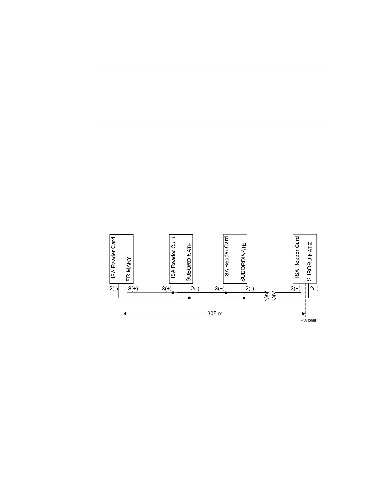
Time Division Multiplexing Connector
Interconnect for time division multiplexing (TDM) is provided by a differential RS-
485 interface with a DB-9 connector located on the expansion connector in slot 2. This
connection provides a synchronization interface between readers to provide multiplex-
ing in time. This interface connection can be daisy-chained from reader to reader dur-
ing installation (Figure D-2) and can operate by synchronizing the readers to each
other by a synchronization pulse from a primary reader. Because there are two sets of
the TDM synchronization pins, one set can be used and the incoming and the second
set can be used for outgoing signals. By daisy-chaining the readers on separate pins,
the downstream side (away from the primary reader) loses synchronization when dis-
connected. TransCore recommends that both upstream and downstream connections
be wired to the same positive (+) and negative (-) pins as shown in Figure D-2.
Figure D-2 Typical TDM Installation
With the use of low-loss/capacitance twisted pair cable, the maximum distance is 305
m (1000 ft), but can vary with installation and type of cable used. The suggested cable
is either Belden 89182 or 8132. Table D-2 shows the pin designations and descriptions
for the TDM connector.