Connector Pin-outs
E-13
Auxiliary Power
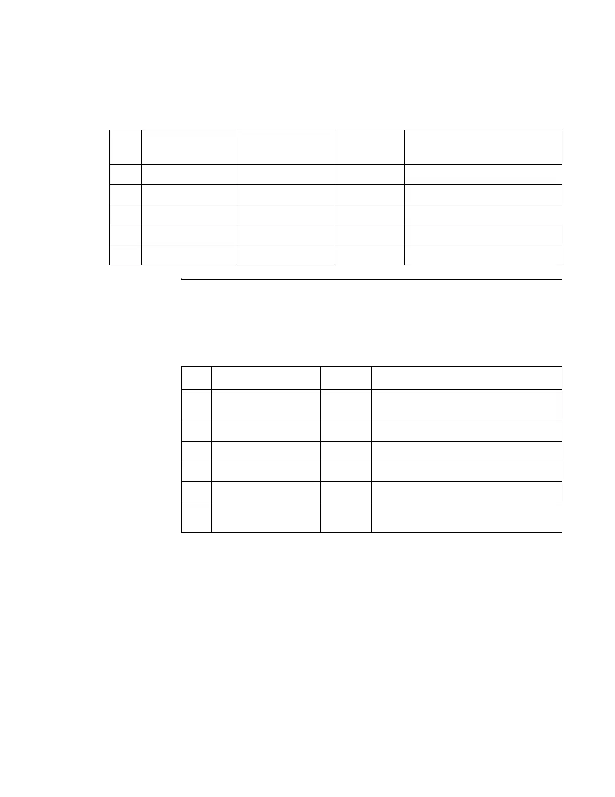
Table E-6 shows the pinout of the auxiliary power connector. Signal I/O is with
respect to the reader logic card.
46 Unused CONT_CW_INP Unused Input - HI to turn CW on
47 Unused Unused Unused N/A
48 Unused Unused Unused N/A
49 Unused Unused Unused N/A
50 Unused Unused Unused N/A
Table E-5 IP Module I/O Connector (continued)
Pin
Slot A (Input/
output)
Slot B (Encode/
Decode)
Slot C
(Spare)
Description
Table E-6 Auxiliary Power Connector
Pin Name Type Description
1 GND Input/
output
Ground
2 +5 VDC Input +5 V power
3 +5 VDC Input +5 V power
4 -12 VDC Input -12 V power
5 +12 VDC Input +12 V power
6 GND Input/
output
Ground