IT2200 Reader System with Multimode Capability Installation & Maintenance/Service Guide
4-12
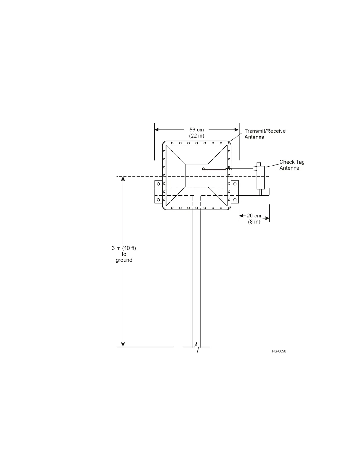
For monostatic configuration, the transmit/receive antenna is mounted on a horizontal
section of 5.0 to 7.6cm (2- to 3-in) wide by 56cm (22-in) long horizontal pipe
mounted 3m (10 ft) above the ground on a vertical pole. The check tag antenna is
mounted next to the transmit/receive antenna. The RF module can be mounted next to
the antenna or in a sheltered location nearby. Figure 4-6 illustrates a typical mono-
static laneside mount.
Figure 4-7 Monostatic Laneside Mount
The exact placement of the antenna for a pillbox installation depends on the site con-
figuration. The placement is the same for both bistatic and monostatic configurations.
Figure 4-8 shows the antenna placement for a typical pillbox installation.