Installing the IT2200 Reader System
4-5
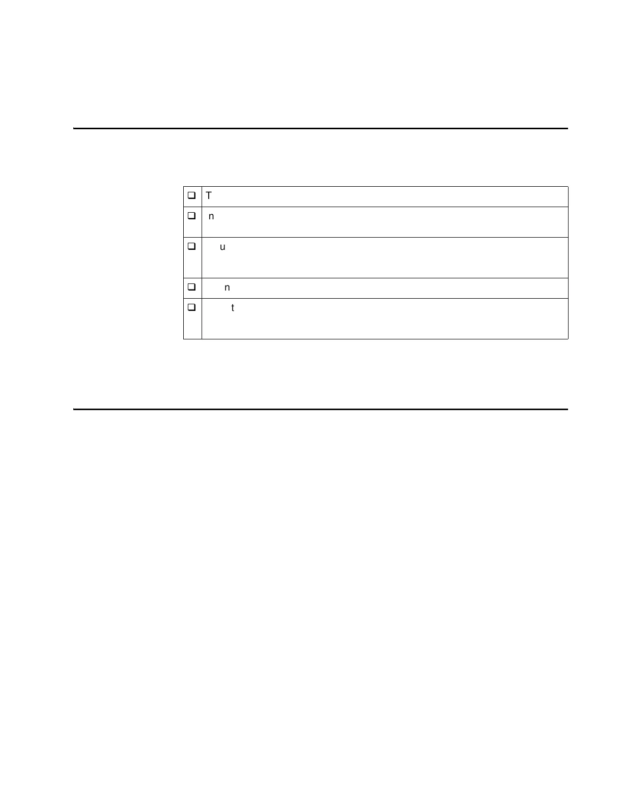
Task Checklist
This checklist summarizes the installation procedure. Instructions for each task are
provided in the “Installing the IT2200 Reader System” section later in this chapter.
After installing a reader system in each lane, it is necessary to tune each lane as
described in Chapter 5, “Tuning the Lane.”
Where to Mount the Components
The location for mounting the components is designated in the site installation plan.
Most Electronic Toll Collection (ETC) site layouts are similar. Four typical mounts
are the canopy, overhead gantry, overpass, and cantilever arm mounts. A fifth config-
uration is the laneside or pillbox antenna mount.
q
Test data cable for proper continuity and isolation.
q
Install reader logic card in host computer. Connect data cable to reader logic
card.
q
Mount RF module. Connect either 19 to 28 VAC or 16 to 28 VDC power to RF
module. Verify voltage with RF module powered (loaded voltage measurement).
Proper voltage is 19 to 28 VAC or 16 to 28 VDC.
q
Connect data cable to RF module.
q
Mount transmit and receive antennas (bistatic installation) or transmit/receive
antenna (monostatic installation), and check tag antennas. Connect antenna(s)
to RF module.