IT2200 Reader System with Multimode Capability Installation & Maintenance/Service Guide
D-4
• Battery Jumper (J8) This jumper must be installed for the battery to backup
SRAM in the event of a power loss. This jumper should remain open while this
reader logic card is in storage.
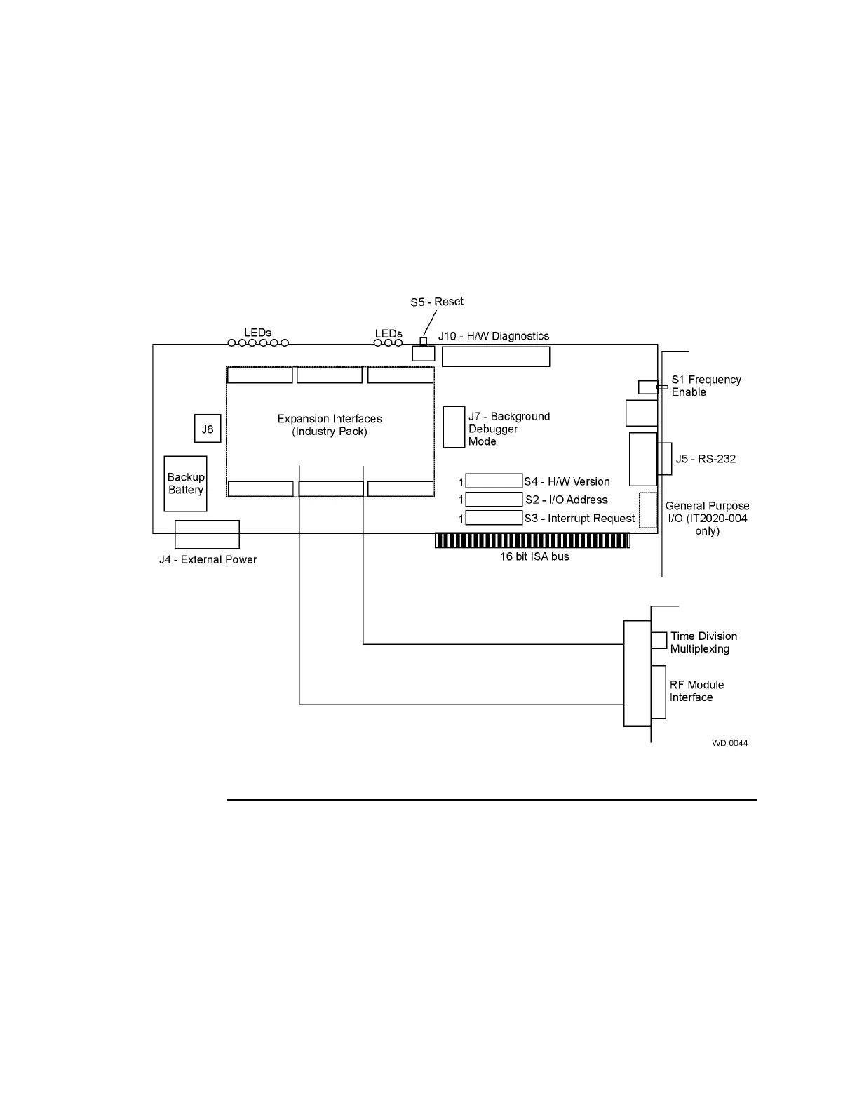
Figure D-1 shows the locations of the IT2020 Reader Logic Card switches.
Figure D-1 Locations of Switches on IT2020 Reader Logic Card
16 Bit ISA Bus
The card edge connector comprises two sets of contact pins on both sides of the board.
The set closest to the PC bracket and the back of the board is the signals for the origi-
nal 8-bit ISA bus. There are 31 contact pins on each side of the board in this set of
signals. The pins designated A1 through A31 are on the component side of the board,
while the pins designated B1 through B31 are on the back side of the board. A1 and
B1 are closest to the bracket end of the PC card. The second set of pins on the board
edge are all of the signals that were added when ISA expanded to a 16-bit data bus.
There are 18 contact pins on each side of the board in this set. The pins designated C1
through C18 are on the component side of the board, while the pins designated D1