IT2200 Reader System with Multimode Capability Installation & Maintenance/Service Guide
D-24
Table D-18 IT2410 Tag Programmer Interconnection
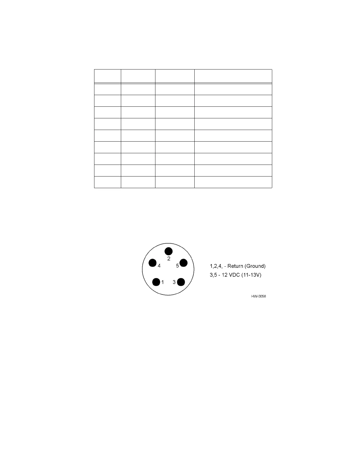
The power is supplied to the programmer through a DIN-9 connector from a 40-W
power switching supply provided with each unit. Figure D-7 shows the connector on
the programmer.
Figure D-7 IT2410 Tag Programmer Power Connections
The power supply used with the programmer provides additional shielding to meet the
Class B, Part 15 FCC requirements. The cable used for the modification is an 18-
AWG, shielded, 2-conductor cable.
Pin Name Type Description
1RSDN/A
a
a. Not internally connected on the IT2410 Tag Programmer
Received line signal detect
2 TxD Output Transmit data
3 RxD Input Receive data
4 DTR Output
b
b. Connected, but not currently used in IT2410 Tag Pro-
grammer firmware
Data terminal ready
5 GND Ground Signal ground
6DSRN/A
a
Data set ready
7 RTS Output
b
Request to send
8 CTS Input
b
Clear to send
9 RI N/A Ring indicator