Connector Pin-outs
E-11
IP Module I/O Connector
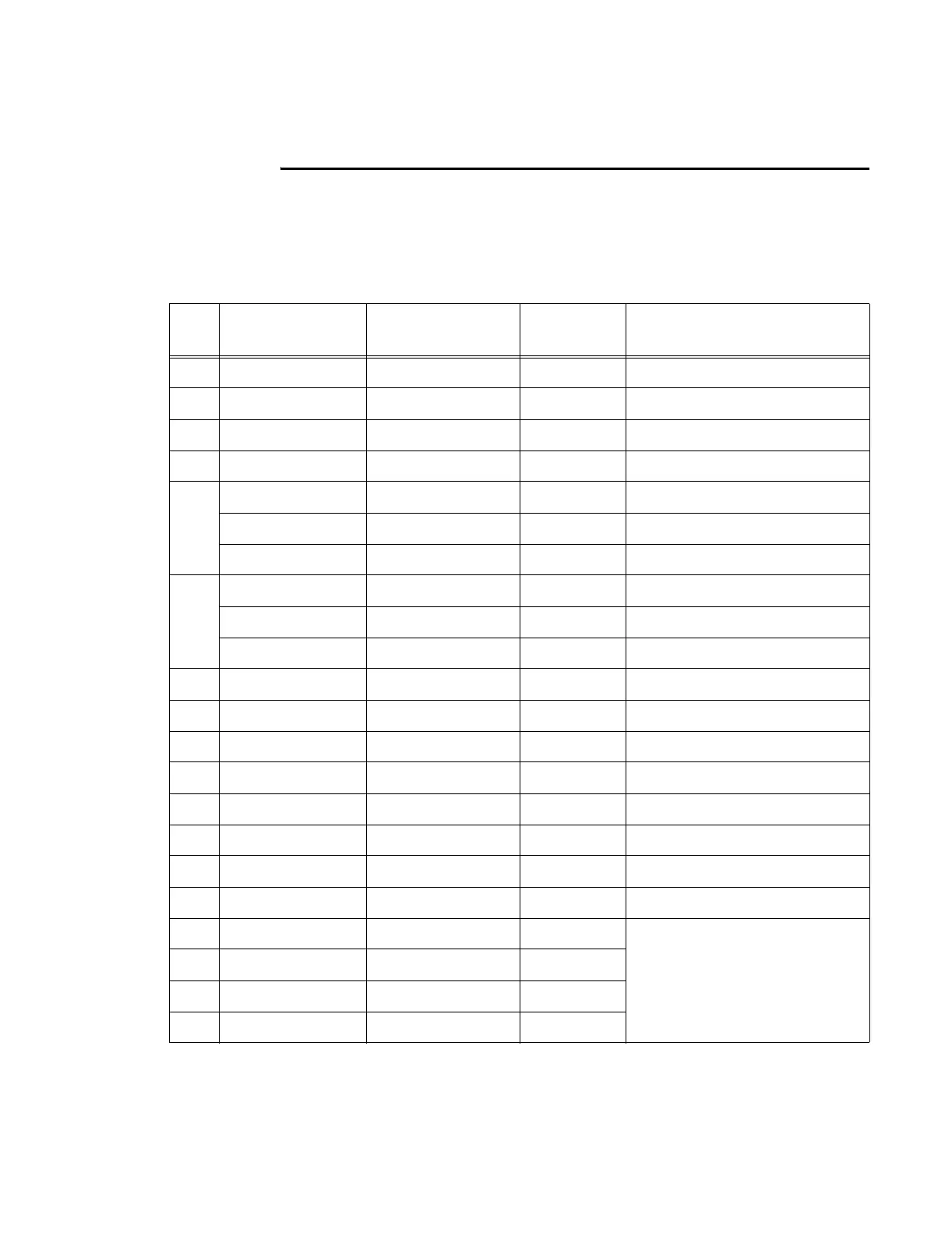
Table E-5 shows the pinout of the IP module I/O connector. Signal I/O is with respect
to the reader logic card.
Table E-5 IP Module I/O Connector
Pin
Slot A (Input/
output)
Slot B (Encode/
Decode)
Slot C
(Spare)
Description
1 IPRXD Unused Unused Responses from RF module
2 B_IP_TXD Unused Unused Commands to RF module
3 GND GND GND Ground
4 GND GND GND Ground
5 DL_RF_ON High to turn downlink power on
BRF_XMITEN Buffered Port C, pin 2 of 360
Unused These two are wired in Flex10K
6 UL_RF_ON High to turn uplink power on
BRF_RCVEN Buffered Port C, pin 8 of 360
Unused These two are wired in Flex10K
7 Unused Unused Unused
8 IT2K_IF_A IT2K_IF_A Unused IT2200 IF channel A from RF
9 IT2K_IF_B IT2K_IF_B Unused IT2200 IF channel B from RF
10 IT2K_IF_C IT2K_IF_C Unused IT2200 IF channel C from RF
11 UNUSED DL_RF_ON Unused High to turn downlink power on
12 UNUSED UL_RF_ON Unused High to turn uplink power on
13 IT2K_MOD IT2K_MOD Unused IT2200 MOD from Flex10K
14 Unused XMTACT_PLS_L Unused Mod out has gone active
15 A_SPARE4 B_SPARE4 C_SPARE4 Extra Via’s added to board for
future upgrade
16 A_SPARE3 B_SPARE3 C_SPARE3
17 A_SPARE2 B_SPARE2 C_SPARE2
18 A_SPARE1 B_SPARE1 C_SPARE1