Tuning the Lane
5-7
1. From the Reader menu, select RF Attenuation. When the RF Attenuation
Parameters screen appears, set the downlink and uplink attenuation to 0, then
click Apply.
2. From the Options menu, select Diagnostics, then Attenuation Statistics. When
the Attenuation Statistics Control screen appears, click Read Frame #07, All
Tags, then click Run.
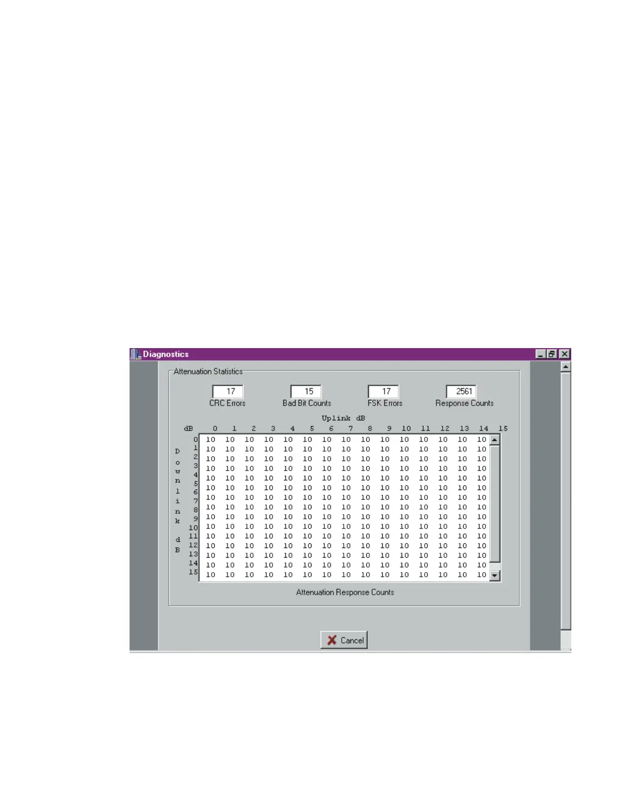
3. After about two minutes, a table of results displays (see Figure 5-2 for sample
results). Save the table using screen capture (press Alt-Print Scrn), paste it into a
word processing program such as Microsoft Word, and assign it a title.
An attenuation response count of 9 or 10 is ideal. A count of 5 at 14dB uplink and
downlink attenuation is acceptable.
If the count at 14dB uplink and downlink attenuation is less than 5, or if the count
at 15dB uplink and downlink attenuation is 0, go to Chapter Chapter 6,
“Troubleshooting the Installation.”
Figure 5-2 Sample RF Attenuation Statistics for Check Tag
4. From the Reader menu, select Check Tag Control. When the Check Tag
Control screen appears, select Check Tag Disabled, then click Apply.