IT2200 Reader System with Multimode Capability Installation & Maintenance/Service Guide
E-4
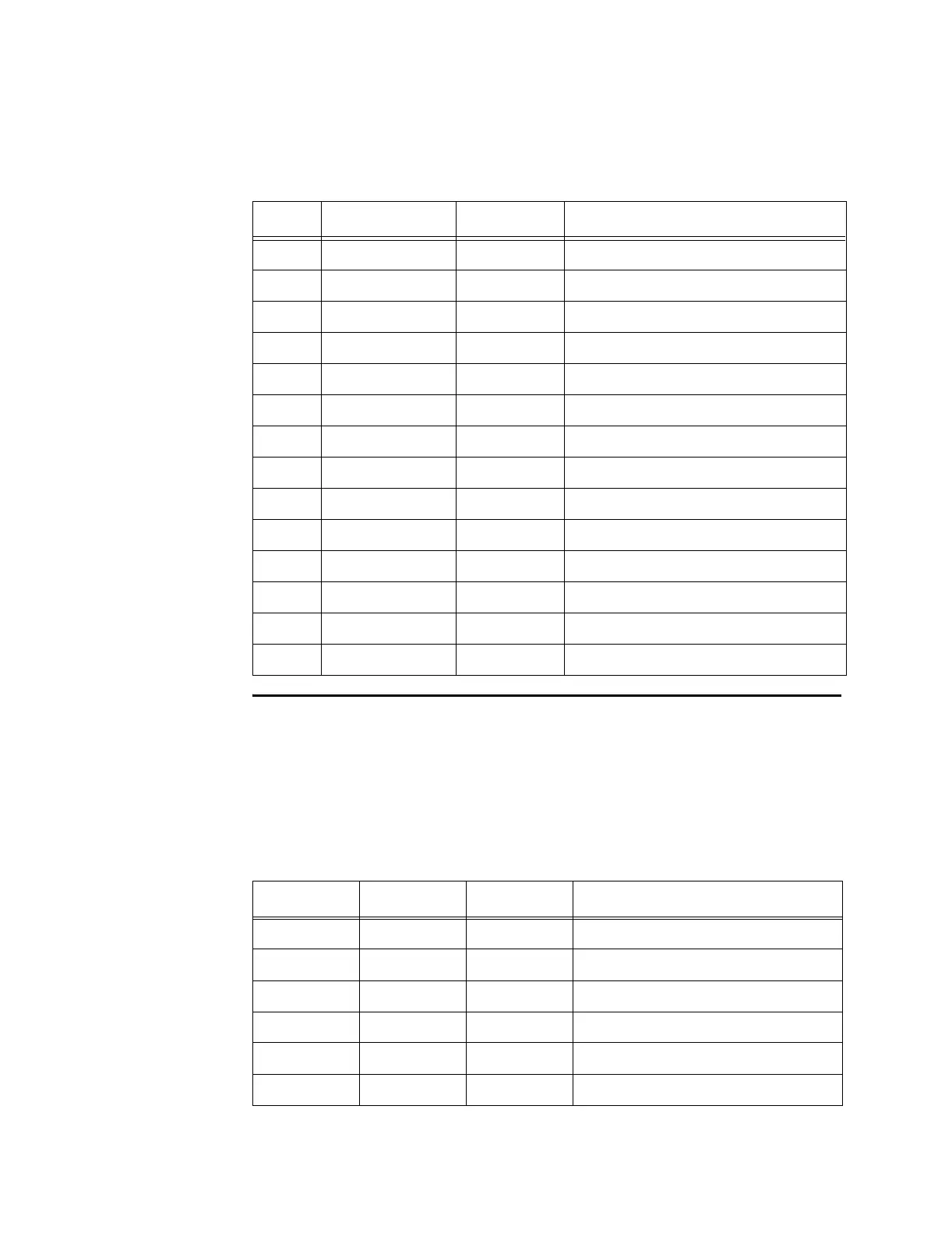
TDM
The TDM (time division multiplexing) connector is located on the reader logic card
RF module interface bracket. The connector is a DB-9. The signals are RS-485. Two
identical pairs are provided for ease of wiring in the field.
Table E-2 shows the pinout of the TDM connector.
12 DL_RF_OFF+ Output RF downlink power on/off, positive
13 Unused N/A N/A
14 IF_A- Input IT2200 tag data, channel A-
15 IF_B+ Input IT2200 tag data, channel B+
16 Unused N/A N/A
17 IF_C- Input IT2200 tag data, channel C-
18 MOD+ Output Downlink modulation data, negative
19 Unused N/A N/A
20 CTL_RCV+ Input/output Communication with RF module
21 Unused N/A N/A
22 CTL_XMT- Output Communication with RF module
23 UL_RF_OFF+ Output RF uplink power on/off, positive
24 Unused N/A N/A
25 DL_RF_OFF- Output RF downlink power on/off, negative
Table E-2 TDM Connector
Pin Name Type Description
1 N/A N/A No connection
2 TDM- Input/output TDM synchronization negative
3 TDM+ Input/output TDM synchronization positive
4 N/A N/A No connection
5 N/A N/A No connection
6 N/A N/A No connection
Table E-1 Tag Data/Control Interface Connector (continued)
Pin Name Type Description