IT2200 Reader System with Multimode Capability Installation & Maintenance/Service Guide
4-14
Table 4-2 Listing of Shorted Pins for Loopback Connector
Installing the IT2020 Reader Logic Card
This section describes the installation of the IT2020 Reader Logic Card in a host com-
puter or lane controller. Details of installation may vary slightly depending on the site
configuration.
Caution
Wear a wrist strap when handling and installing the reader logic card. Failure to do
so can result in ESD damage to the card.
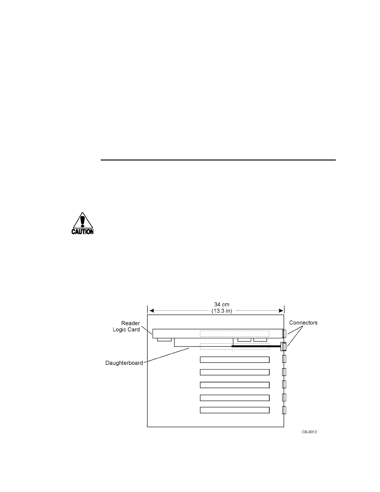
Figure 4-9 shows a reader logic card installed in a typical host computer or lane con-
troller chassis. Because of its daughterboard and two connector panels, the reader
logic card occupies two slots. One ISA slot provides power and communications
through the card’s edge connector and provides access to the frequency mode switch
and RS-232 port on the back of the card. The other slot provides space for the RF
module interface.
Figure 4-9 IT2020 Reader Logic Card Installed in Typical Host Computer or
Lane Controller Chassis (top view)
1 - 15
3 - 14
4 - 18
6 - 17
8 - 22
9 - 20
11 - 25
12 - 23