IT2200 Reader System with Multimode Capability Installation & Maintenance/Service Guide
3-8
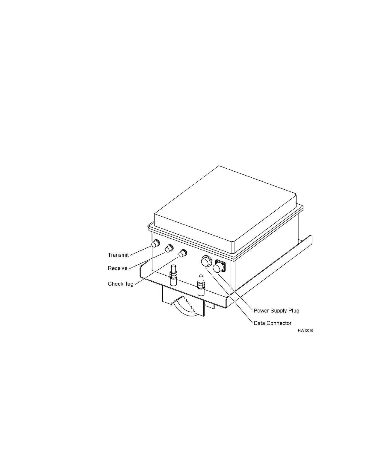
The RF module housing consists of the following components:
• Fiberglass enclosure
• Bulkhead Type N connectors for antenna connections
• Bulkhead circular waterproof connectors for power and interface
• Stainless steel mounting hardware
The RF module connects to a 19- to 28-VAC or 16- to 28-VDC power source and
interfaces back to the lane controller and the IT2020 Reader Logic Card. These
connections are illustrated in Figure 3-4 (bistatic) and Figure 3-5 (monostatic).
Figure 3-4 IT2611 RF Module Connections (Bistatic Configuration)