System Components
3-7
Because the IT2020 Reader Logic Card is integrated into the lane controller or host
computer, lightning protection is unnecessary at the reader logic card; however,
lightning protection is provided with the RF module. The RF module is contained in
the vicinity of the antenna housing for simplified installation and maintenance.
External signals are optically isolated to ensure that any potentially damaging
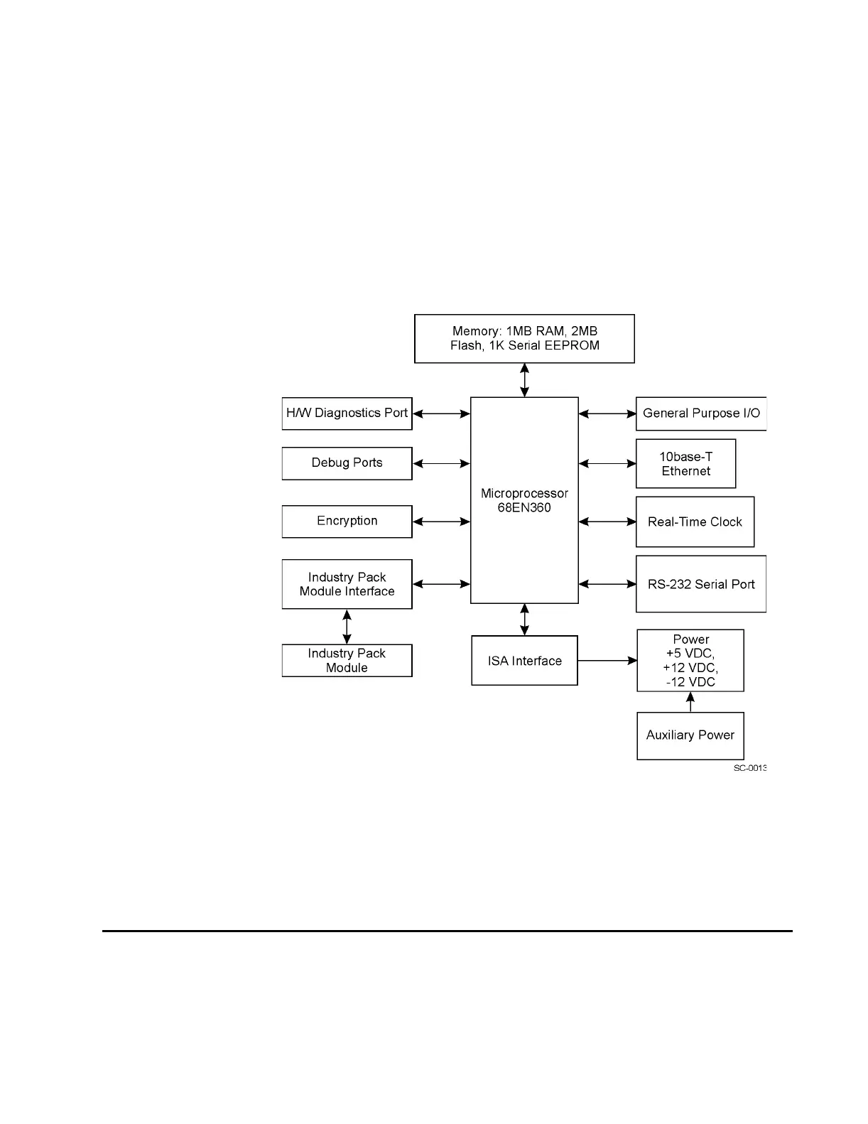
transients do not propagate into the reader. A block diagram of the IT2020 Reader
Logic Card is shown in Figure 3-3.
Figure 3-3 IT2020 Reader Logic Card Block Diagram
The reader logic card acts as the carrier for industry pack (IP) modules that expand the
reader’s functionality. The IP modules are expansion boards that interface to other
processing, status, and control components, such as the RF module. One spare IP slot
allows for an additional module to interface with the reader logic card.
IT2611 RF Module (Bistatic and Monostatic)
The IT2611 RF Module communicates with the IT2020 Reader Logic Card and the
antennas to provide two-way RF communications with tags. It is mounted near the
antennas to reduce signal losses to and from the antennas.