IT2200 Reader System with Multimode Capability Installation & Maintenance/Service Guide
5-6
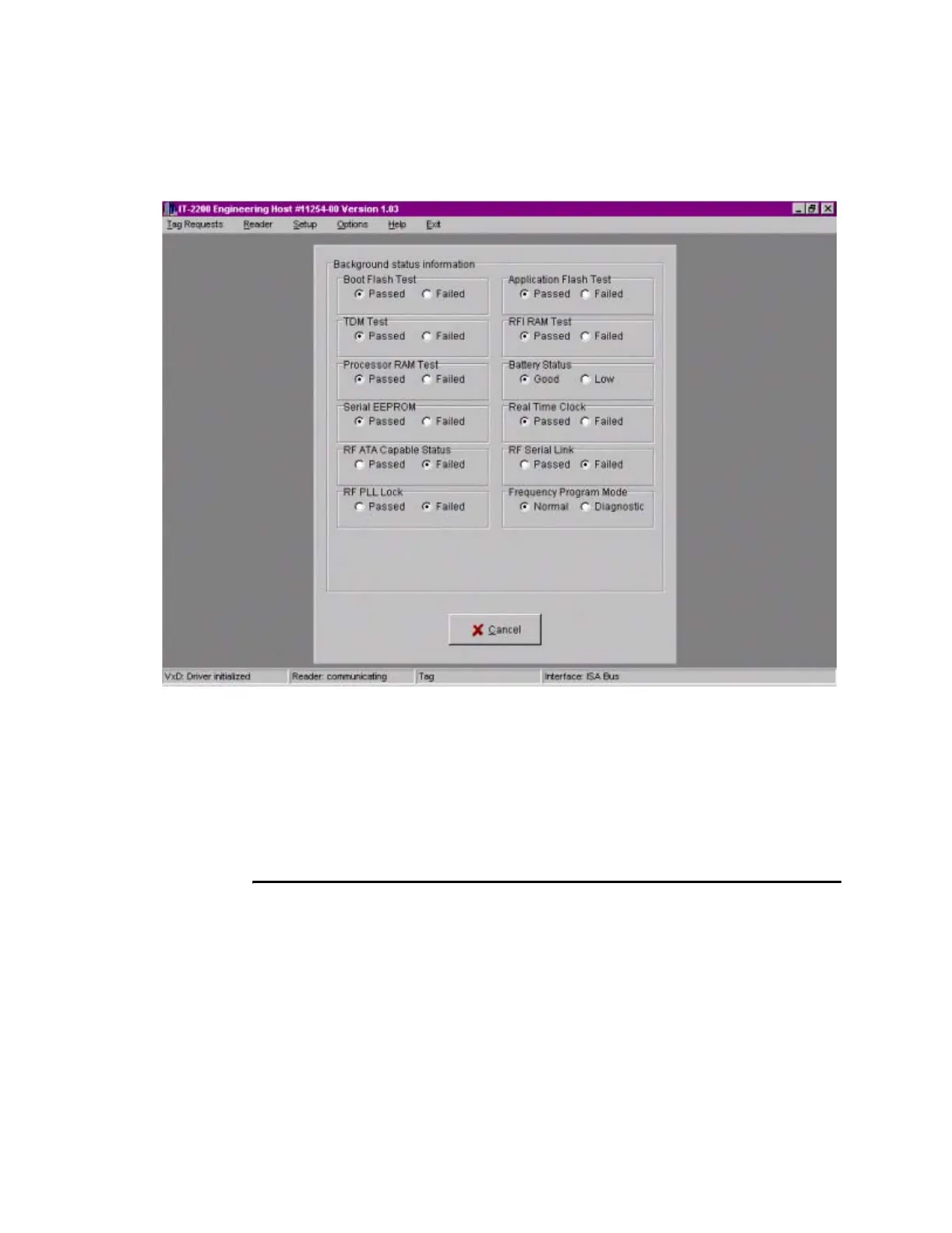
Figure 5-1 Background Status Information Screen
If the system is operating correctly, all Passed blocks on the diagnostics page are
checked. Figure 5-1 shows a failure of the RF Data EEPROM, RF PLL Lock, and
RF Serial Link tests. Any condition that results in a Fail status must be corrected
before the testing proceeds. See Chapter Chapter 6, “Troubleshooting the
Installation,” for corrective actions.
5. Click Cancel to clear the Background status information screen.
Lane Tag Test
This procedure determines the correct RF attenuation settings for the installed reader
system.
If more than one lane is to be tuned, the other lanes should be operating to obtain valid
attenuation parameters. This might not be practical for the initial tuning, but final tun-
ing must be performed with all lanes operating. For untuned lanes, set the attenuation
to 9dB uplink and downlink. When these lanes are finally tuned, if their attenuation
settings differ by more than 2dB from the selected 9dB, some repeat tuning might be
necessary in other lanes.