IT2200 Reader System with Multimode Capability Installation & Maintenance/Service Guide
4-4
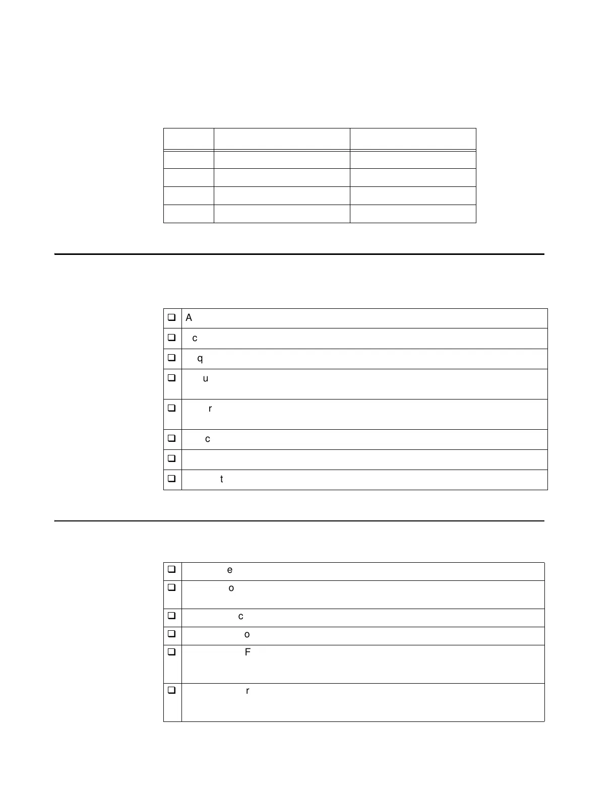
Table 4-1 Example Frequency Plan for Four-Lane Plaza
Site Preparation Checklist
Prepare the site according to the design parameters determined by your system inte-
grator. Some of the tasks you should complete, depending on the individual site, are
Components Checklist
Ensure you have the following components available for each lane to be installed:
Lane Downlink Frequency Uplink Frequency
1 918.75 MHz 903.00 MHz
2 918.75 MHz 912.00 MHz
3 918.75 MHz 903.00 MHz
4 918.75 MHz 912.00 MHz
q
Acquire a construction license.
q
Acquire an FCC license.
q
Acquire an environmental assessment permit.
q
Ensure that you have assembled all the lights, buzzers, and vehicle detectors
that will interface with the system.
q
Ensure that you have software that allows a PC or laptop to interface with the
reader firmware.
q
Pull communications, coaxial, and power cables through outdoor-grade conduit.
q
Ensure that construction work required for mounting the equipment is completed.
q
Ensure that 120 V AC service is available.
q
IT2020 Reader Logic Card
q
One or two AA3152 or AA3153 antennas (depending on whether the installation
is monostatic or bistatic, and plaza type)
q
IT2502 Check Tag Antenna
q
IT2611 RF Module
q
One or two RF-grade coaxial cables with Type N connectors to link the
antennas to the RF module (depending on whether installation is monostatic or
bistatic)
q
Tag data/control cable (data cable) to link the RF module to the reader logic
card. The cable must have a DB-25 plug connector and a 26-pin circular socket
connector (Souriau 851-06RJ16-26S50 or equivalent).