IT2200 Reader System with Multimode Capability Installation & Maintenance/Service Guide
3-26
As shown in Figure 3-13, all indicators are located on the top face of the programmer.
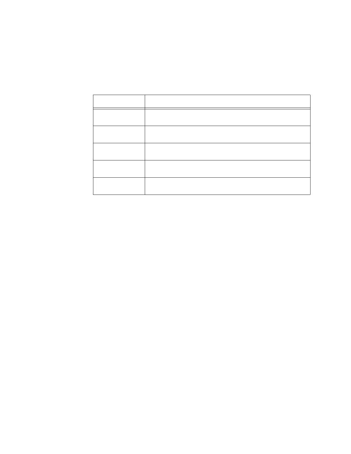
The functional indicators of the tag programmer are listed in Table 3-4.
Table 3-4 IT2410 Tag Programmer Indicator LEDs and Descriptions
The tag programmer also has the following features:
• FCC compliant—The programmer has been tested and found to comply with the
limits established by the FCC for a Class A computing device.
• AC power—The programmer is powered from a standard 120 VAC outlet. A UL-
approved 12 VDC power module is included.
Indicator LED Description
PROGRAM
(GREEN)
The tag is being programmed with user-specified data.
VERIFY
(GREEN)
The tag programmer has read valid data from the specified tag
frame.
ERROR (RED) The tag programmer has detected an error in the programming
or verifying process or during other operations.
POWER
(GREEN)
Power is being supplied to the tag programmer.
READY
(GREEN)
The tag programmer is ready to accept commands from the
PC.