Installing the IT2200 Reader System
4-15
To install the reader logic card
1. Connect the loopback connector to the data cable, then test the cable for
continuity and isolation.
2. Remove the reader logic card, which is still in its ESD protective bag, from the
shipping box.
3. Put on the protective wrist strap; be sure it is properly grounded.
4. Remove the reader logic card from the ESD protective bag.
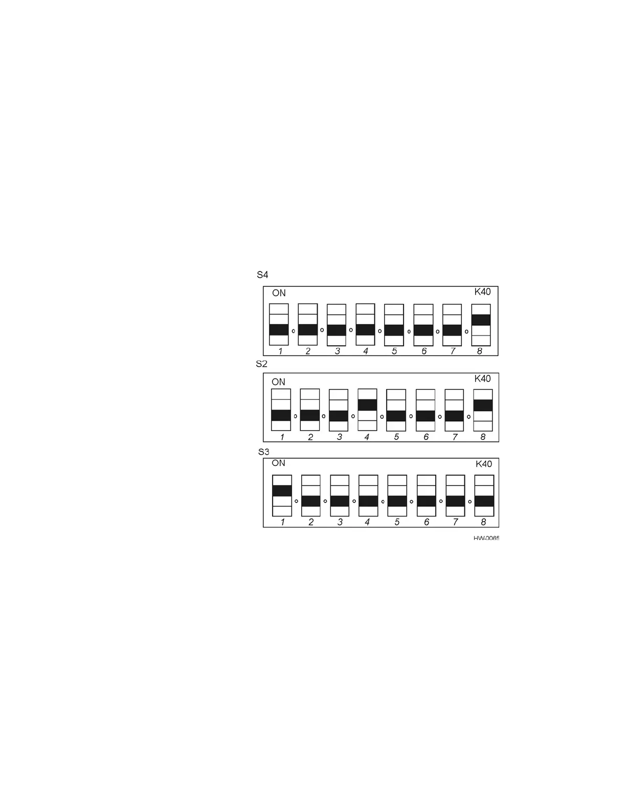
5. Verify that dipswitches S2, S3, and S4 are still set to the factory settings shown in
Figure 4-10. Refer to page D-3 in Appendix D to this document for configuration
settings information.
Figure 4-10 IT2020 Reader Logic Card Factory Dipswitch Settings
6. Set the frequency-enable switch (S1) to the left (normal) position as shown in
Figure 4-11.