Hardware Interfaces
D-11
IT2020 Reader Logic Card Interface
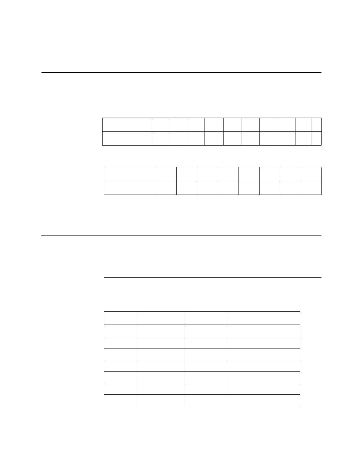
This section shows the input/output and interrupt request line factory (default) config-
uration settings (Table D-7 and Table D-8) for the IT2020 Reader Logic Card.
Table D-7 IT2020 Reader Logic Card Default I/O Settings
Table D-8 IT2020 Reader Logic Card Default IRQ Settings
Note: Only one IRQ switch should be selected. If more than one switch is set, multiple
interrupts will occur.
Pin Designations
Tables D-9 through D-13 list the pin specifications for the IT2020 Reader Logic Card,
IT2611 RF Module, and IT2410 Tag Programmer. Figure D-3 shows the locations of
the LEDs on the IT2020 Reader Logic Board.
IT2020 ISA Card Interface Connector
Switch Number
8765 4321 xx
Switch State
on off off off on off off off x x
Switch Number
87654321
IRQ
15 14 12 11 10 7 6 5
Table D-9 ISA Bus Pin Definition
Pin Signal In/Out Description
A1 IOCHK_L Out I/O channel check
A2 D7 In/Out Data bus, bit 7
A3 D6 In/Out Data bus, bit 6
A4 D5 In/Out Data bus, bit 5
A5 D4 In/Out Data bus, bit 4
A6 D3 In/Out Data bus, bit 3
A7 D2 In/Out Data bus, bit 2