Installing the IT2200 Reader System
4-19
To install the RF module
1. Locate the RF module atop the mounting pipe and insert a U-bolt around the pole
and up through the bracket. Place a spacer over each section of the U-bolt
protruding through the bracket and place a lock washer and nut over each side of
the U-bolt. Repeat for the other U-bolt.
Note: Depending on pole diameter, spacers may or may not be needed.
2. Tighten nuts with torque wrench to 68 N-m (50 ft-lb). Tighten second nut over
first nut to lock it in place.
3. Check that 19 to 28 VAC or 16 to 28 VDC power is available at the module end
of the power cable. Measure the voltage across pins A and C of the power cable
connector.
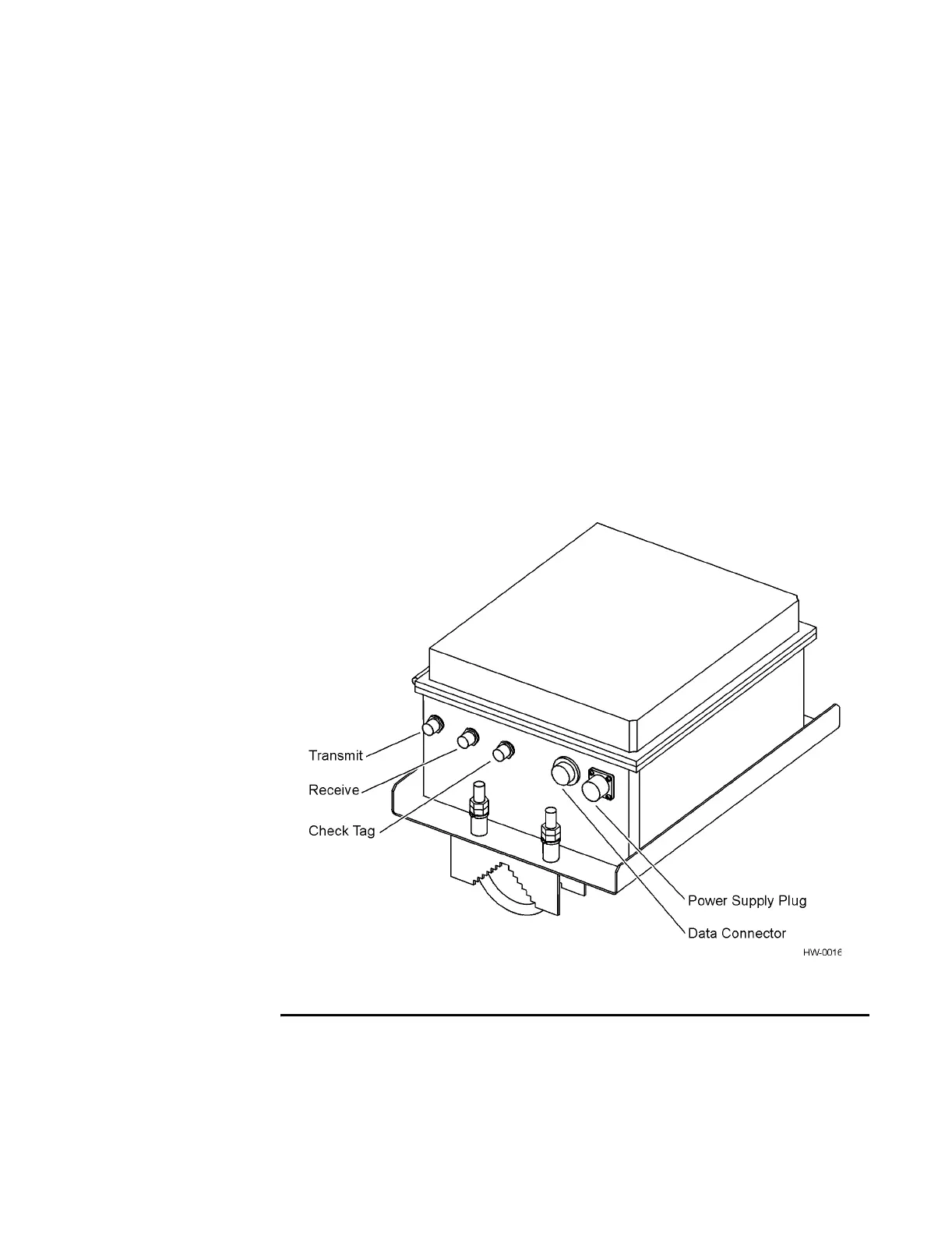
4. Connect the power cable to the RF module’s power supply plug (Figure 4-14).
5. Connect the data cable to the RF module’s data connector.
Figure 4-14 IT2611 RF Module Connectors (Monostatic RF Module Shown)
Installing the AA3152 UTA
The UTA is mounted on a 5.0 to 7.6cm (2- to 3-in) pipe to accommodate various
angles for lane tuning. Two UTAs are required for each dedicated or mixed-use lane
in a bistatic configuration. One UTA is required for each dedicated or mixed-use lane