IT2200 Reader System with Multimode Capability Installation & Maintenance/Service Guide
4-16
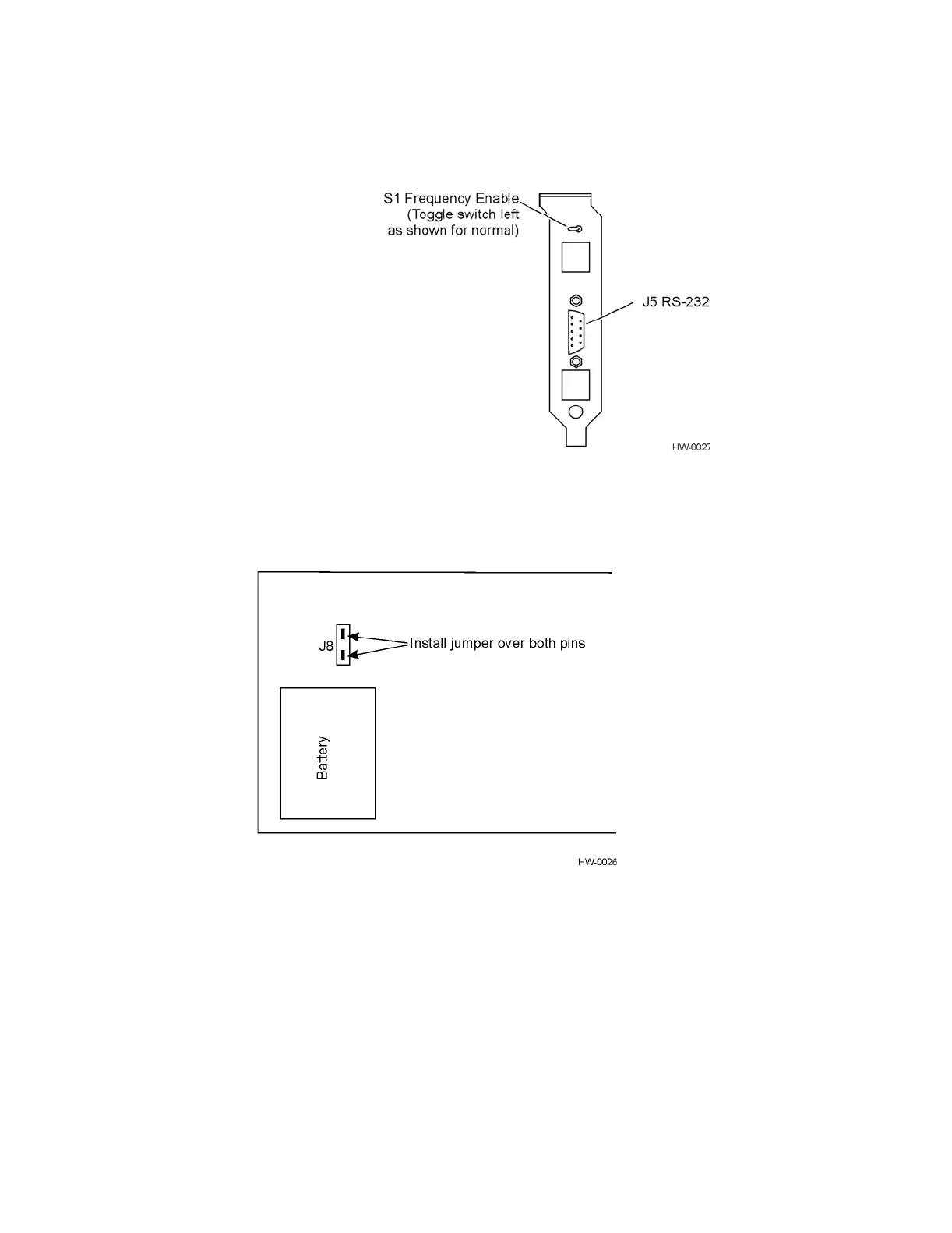
Figure 4-11 Frequency Enable Switch on Rear of IT2020 Reader Logic Card
7. Locate the battery jumper (might be on J8 or be loose in the ESD bag) and install
over both J8 pins (see Figure 4-12).
Figure 4-12 Location of Battery Jumper (J8) in Relation to Battery
8. Turn off the host computer.
9. Insert the reader logic card in an ISA slot in the host computer. Be sure the card’s
edge connector is firmly seated, then secure the card with the retaining screw.
10. Install the reader logic card’s RF interface connector in a slot next to the reader
logic card, then secure the connector with the retaining screw.
11. Do not turn on the host computer until ready to test the system as described in
Chapter 5.