IT2200 Reader System with Multimode Capability Installation & Maintenance/Service Guide
D-18
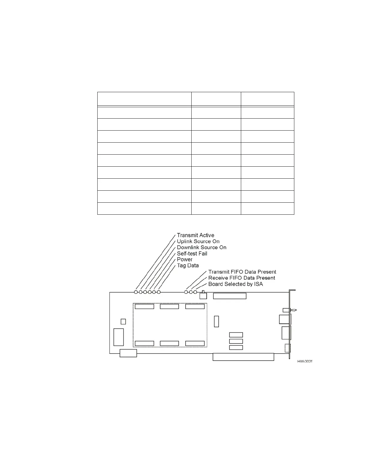
Figure D-3 Locations of LEDs on IT2020 Reader Logic Card
The reader-to-RF module interfaces to the reader logic card by nonformatted differen-
tial signals. In addition to these nonformatted signals, for the bistatic version there are
two communications lines (one receive and one transmit) to send commands to the RF
module in the form of frequency control, power attenuation, and check tag command.
The reader-RF module also connects to the transmit (bistatic downlink), receive
(bistatic uplink), transmit/receive (monostatic downlink/uplink), and check tag anten-
nas (both bistatic and monostatic) (see Figure D-4 and Figure D-5).
Table D-13 LEDs
Action Color Stretched
Board Selected by ISA Green No
Receive FIFO Data Present Red No
Transmit FIFO Data Present Yellow Yes
Tag Data Green Yes
Power Green No
Self-Test Fail Red No
Downlink Source On Yellow No
Uplink Source On Red No
Transmit Active Yellow Yes