Hardware Interfaces
D-7
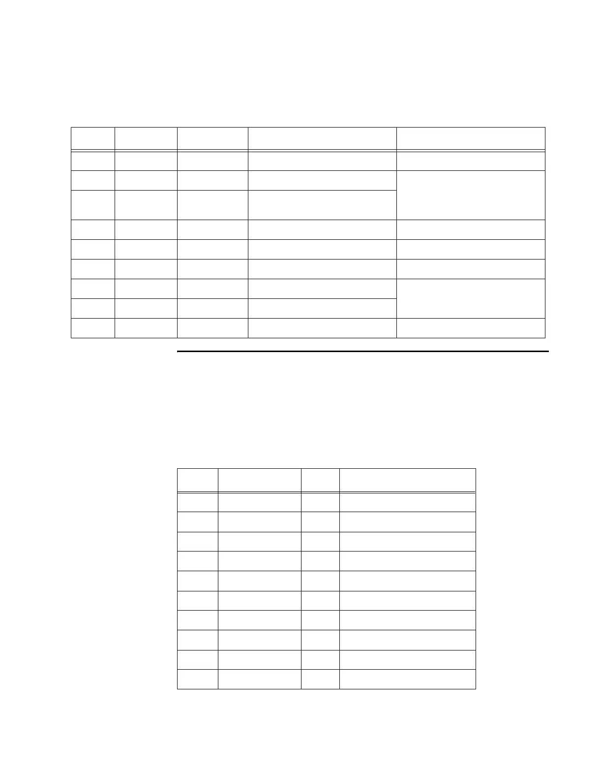
Table D-2 TDM Connector
Background Debugger Connector
The background debugger (BDM) connector is a 10-pin, 0.1-center dual-row header,
with a configuration is 2 by 5. This connector is used for debugging only and is a
Motorola proprietary interface.
Table D-3 shows the pin designations and descriptions for the BDM connector.
Table D-3 BDM Connector
Pin Name Type Description Recommended Connection
1 N/C N/A No connection
2 TDM (-) In/Out TDM synchronization negative Connect all negative
connections together. Connect
all positive connections
together.
3 TDM (+) In/Out TDM synchronization positive
4 N/C N/A No connection
5 N/C N/A No connection
6 N/C N/A No connection
7 TDM (+) In/Out TDM synchronization positive
Ignore pins 7 and 8.
8 TDM (-) In/Out TDM synchronization negative
9 N/C N/A No connection
Pin Signal I/O Description
1 DS_L Data strobe
2 BERR_L Bus error
3 GND Ground
4 BKPT/DSCLK Development serial clock
5 GND Ground
6 FREEZE Breakpoint acknowledge
7 RESET_L Hard system reset
8 IFETCH/DSI Development serial input
9VCC +5 VDC
10 IPIPE0/DSO Development serial output