E-3
Appendix E
Connector Pin-outs
This appendix provides connector pin-out information for the IT2020
Reader Logic Card and the IT2611 RF Module.
IT2020 Reader Logic Card
This section provides pin-outs for the interface connectors on the IT2020 Reader
Logic Card.
Tag Data/Control
The communication path between the IT2020 Reader Logic Card and the IT2611 RF
Module runs through the input/output (I/O) module that is connected to IP slot A. The
I/O module connects to the RF module through a ribbon cable terminating at a DB-25
connector mounted on the RF module interface bracket. The tag data/control cable
from the RF module connects to this DB-25 connector.
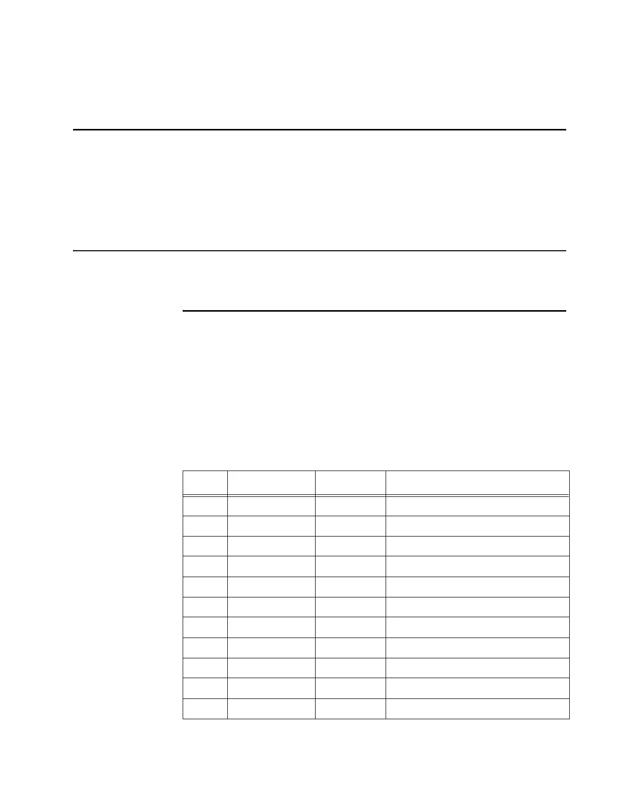
Table E-1 shows the pinout of the DB-25 connector. Signal I/O is with respect to the
reader logic card.
Table E-1 Tag Data/Control Interface Connector
Pin Name Type Description
1 IF_A+ Input IT2200 tag data, channel A+
2 Unused N/A N/A
3 IF_B- Input IT2200 tag data, channel B-
4 IF_C+ Input IT2200 tag data, channel C+
5 Unused N/A N/A
6 MOD- Output Downlink modulation data, negative
7 Unused N/A N/A
8 CTL_RCV- Input Communication with RF module
9 CTL_XMT+ Output Communication with RF module
10 Unused N/A N/A
11 UL_RF_OFF- Output RF uplink power on/off, negative