Hardware Interfaces
D-5
through D18 are on the back side of the board. Pins C1 and D1 are closest to the
bracket end of the PC card. Signal I/O is with respect to the ISA reader.
Optional External Power
Typically, the logic card receives power from the ISA bus. When the card is inserted
into an ISA bus backplane, this connector is not used. If the logic card is used in an
application where no ISA bus is present, the card receives power through this connec-
tor. Table D-1 lists definitions of the connector pins and the power supply require-
ments. The signal I/O is with respect to the ISA reader.
Expansion Interfaces (Industry Pack)
The ISA reader provides a minimum of two expansion slots on a mezzanine bus that
follows the definition of the Industry Pack (IP) Bus VITA 4-1995 draft document.
The clock speed for this bus is 8 MHz. The physical interface is made with two Type-
D connectors per each expansion slot. The connectors are AMP, Incorporated, part
173280-3 or equivalent on the ISA board. One connector contains all of the bus inter-
face and logic and the second is used for all user-defined I/O.
For implementing the IT2000 Encoder/Decoder daughterboard, the I/O connector
contains connections for a UART interface from the 68360 for the control interface to
the RF module, and discrete outputs used to control the RF power on/off of the RF
uplink and RF downlink of the RF module. All unused pins are reserved.
Signal I/O is with respect to the ISA printed wiring assembly (PWA).
The RF module interface connector is a 25-pin Type-D (DB-25F) socket connector. It
provides an interface to the RF module portion of the reader.
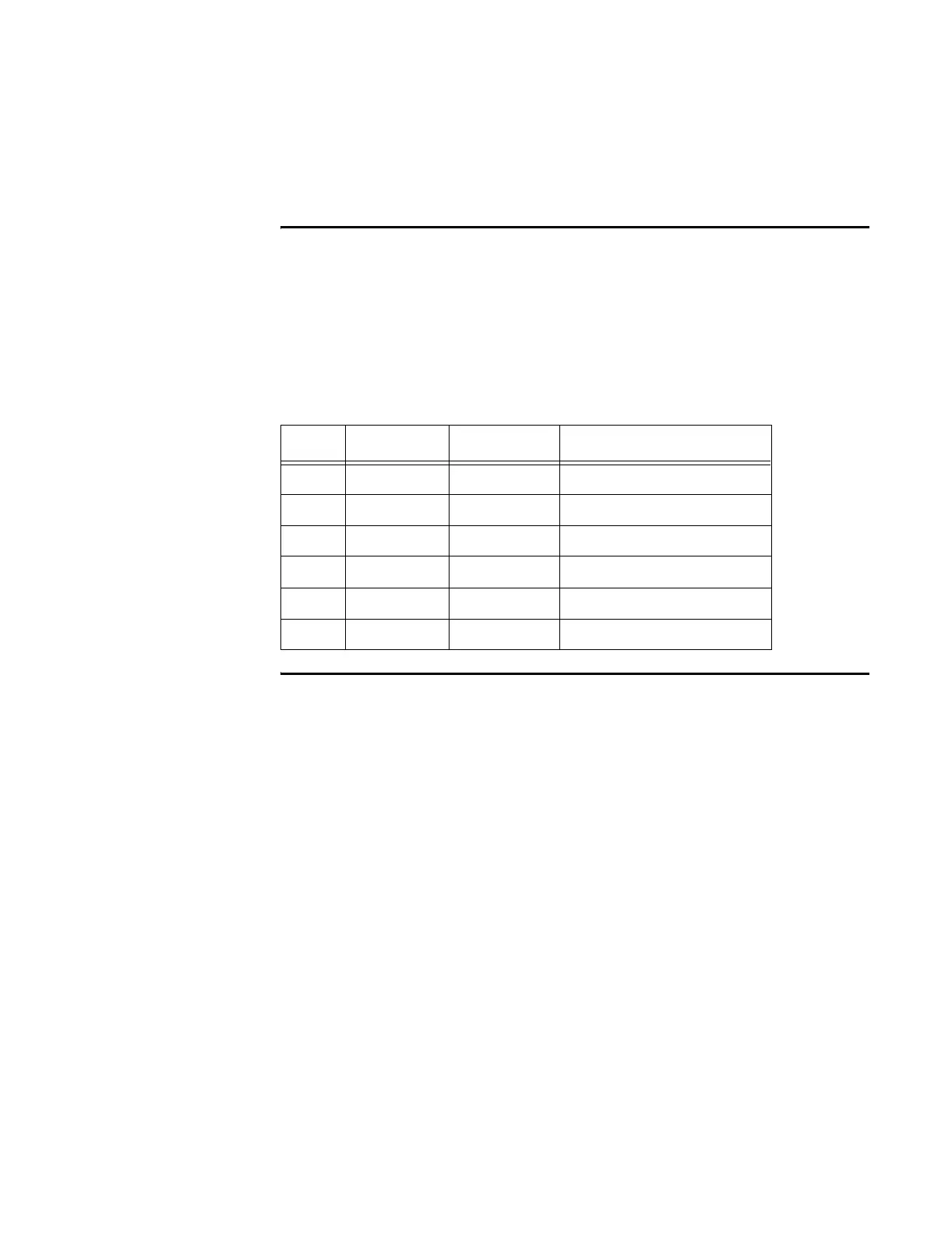
Table D-1 Optional External Power Pin Definition
Pin Signal In/Out Description
1 GND In/Out Ground
2 +5 VDC In +5 volt power
3 + 5VDC In +5 volt power
4 -12 VDC In -12 volt power
5 +12 VDC In +12 volt power
6 GND In/Out Ground