Connector Pin-outs
E-5
ISA Bus
The IT2020’s edge connector has two sets of contact fingers on each side of the board.
Pins A1 through A31 and C1 through C18 are on the component side of the card. Pins
B1 through B31 and D1 through D18 are on the other side. For all pin sets, the lower
numbers are toward the bracket end of the card.
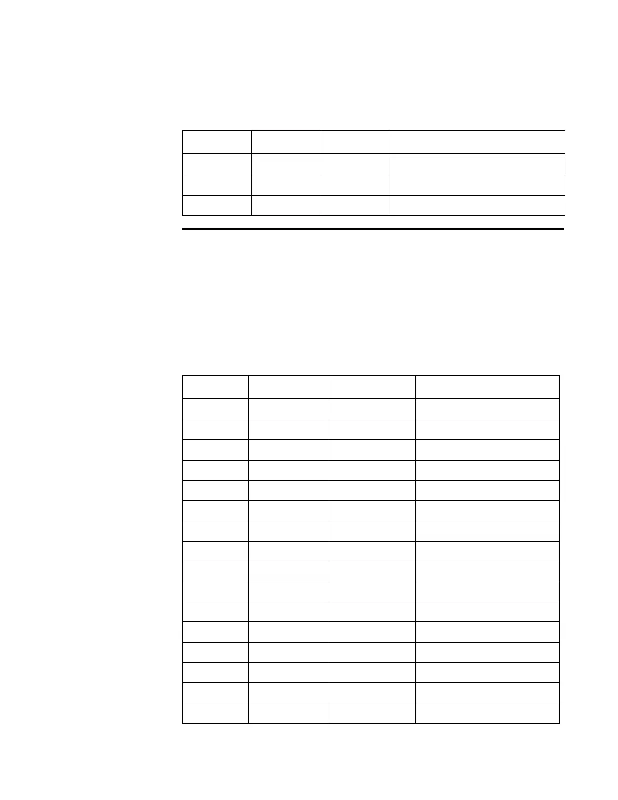
Table E-3 shows the pinout of the ISA bus connector. Signal I/O is with respect to the
reader logic card.
7 TDM+ Input/output TDM synchronization positive
8 TDM- Input/output TDM synchronization negative
9 N/A N/A No connection
Table E-3 ISA Bus Pin Definition
Pin Name Type Description
A1 IOCHK_L Output I/O channel check
A2 D7 Input/output Data bus, bit 7
A3 D6 Input/output Data bus, bit 6
A4 D5 Input/output Data bus, bit 5
A5 D4 Input/output Data bus, bit 4
A6 D3 Input/output Data bus, bit 3
A7 D2 Input/output Data bus, bit 2
A8 D1 Input/output Data bus, bit 1
A9 D0 Input/output Data bus, bit 0
A10 CHRDY Output I/O channel ready
A11 AEN Input Address enable
A12 SA19 Input System address, bit 19
A13 SA18 Input System address, bit 18
A14 SA17 Input System address, bit 17
A15 SA16 Input System address, bit 16
A16 SA15 Input System address, bit 15
Table E-2 TDM Connector (continued)
Pin Name Type Description