IT2200 Reader System with Multimode Capability Installation & Maintenance/Service Guide
6-10
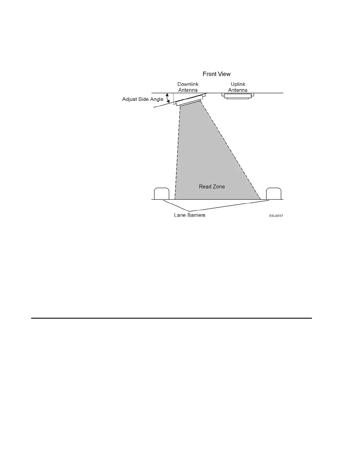
Figure 6-4 Downlink Antenna Side Angle Adjustment
Adjusting the Antenna Placement
Besides adjusting the antenna angles, you can also move the antenna farther back into
its overhead location so that the read zone does not extend as far in front of the trans-
action area. By shortening the read zone you may be able to reduce the required RF
output power. This will result in reduced probability of cross-lane interference.
Other Site Modifications
In rare instances, applying radar absorbing foam to fixed areas of the toll plaza (e.g.,
metal roof) may reduce the incidence of interference.
Troubleshooting Indications and Actions
This section includes troubleshooting information for the listed problems. Refer to the
appropriate table for detailed instructions. If applicable, the table refers you to the
removal and replacement procedure later in this section.
• Table 6-3, ”Failure Indicated by Host Software Diagnostics
• Table 6-4, ”Failure During Check Tag Test
• Table 6-5, ”Unacceptable RF Attenuation Statistics Using Check Tag
• Table 6-6, ”Unacceptable RF Attenuation Statistics Using Vehicle-Mounted Tag
• Table 6-7, ”Self-Test Fail LED on Reader Logic Card Lights