Hardware Interfaces
D-15
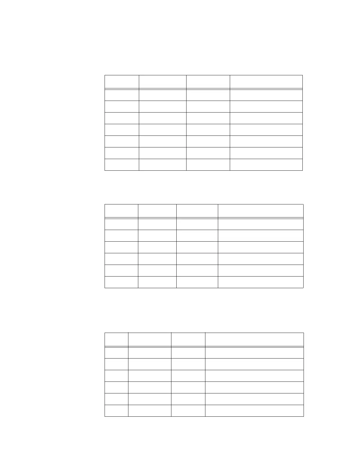
Table D-10 Optional External Power Pin Definition
D12 DAK6_L In DMA acknowledge 6
D13 DRQ6 Out DMA request 6
D14 DAK7_L In DMA acknowledge 7
D15 DRQ7 Out DMA request 7
D16 +5 VDC +5 volt power
D17 MASTER_L Out Primary
D18 GND In/Out Ground
Pin Signal In/Out Description
1 GND In/Out Ground
2 +5 VDC In +5 volt power
3 + 5VDC In +5 volt power
4 -12 VDC In -12 volt power
5 +12 VDC In +12 volt power
6 GND In/Out Ground
Table D-11 IP Module Logic Interface Connector
Pin Signal In/Out Description
1 GND Out Ground
2 CLK Out 8-MHz Clock
3 RESET_L Out Reset signal (active low)
4 D0 In/Out Data bit 0
5 D1 In/Out Data bit 1
6 D2 In/Out Data bit 2
Table D-9 ISA Bus Pin Definition (continued)
Pin Signal In/Out Description