IT2200 Reader System with Multimode Capability Installation & Maintenance/Service Guide
D-16
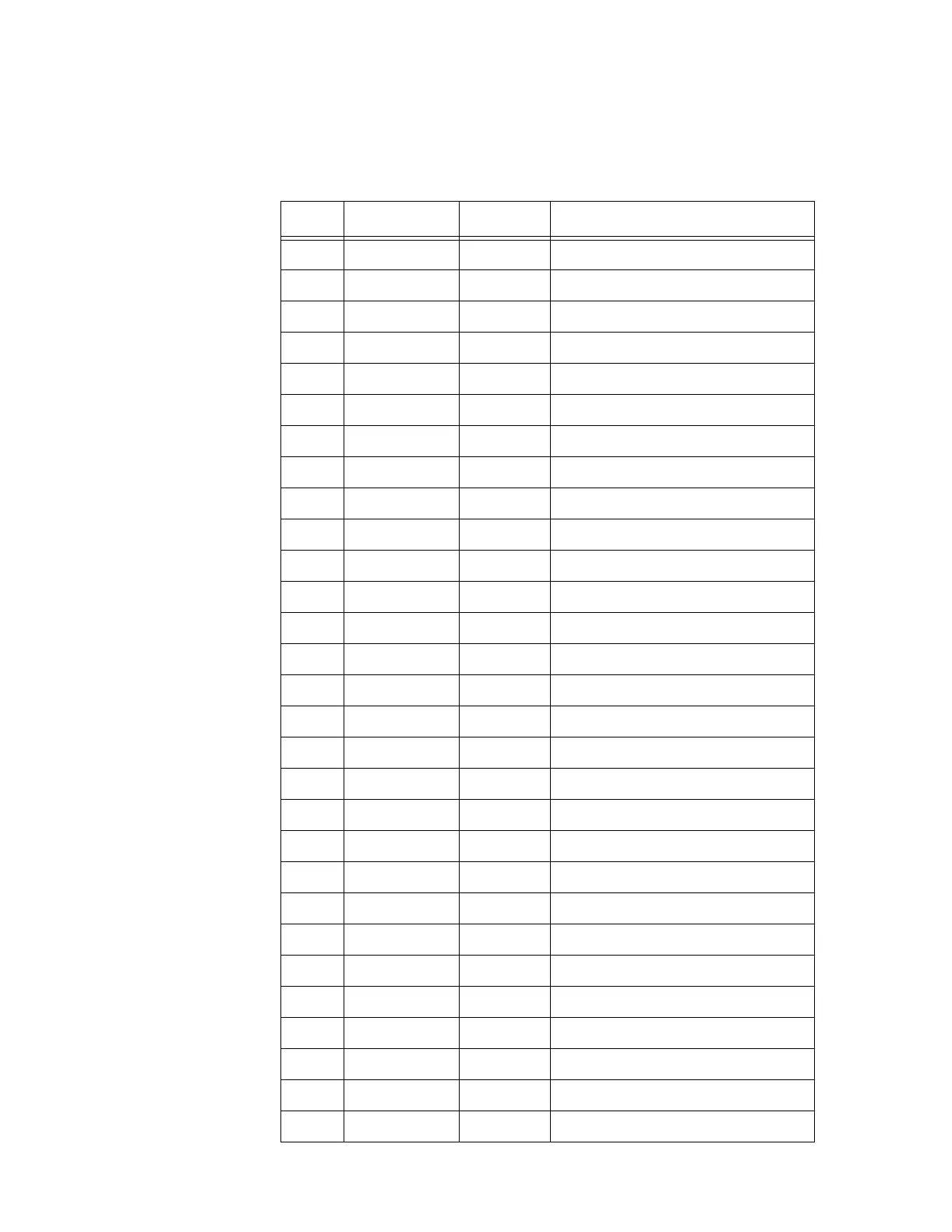
7 D3 In/Out Data bit 3
8 D4 In/Out Data bit 4
9 D5 In/Out Data bit 5
10 D6 In/Out Data bit 6
11 D7 In/Out Data bit 7
12 D8 In/Out Data bit 8
13 D9 In/Out Data bit 9
14 D10 In/Out Data bit 10
15 D11 In/Out Data bit 11
16 D12 In/Out Data bit 12
17 D13 In/Out Data bit 13
18 D14 In/Out Data bit 14
19 D15 In/Out Data bit 15
20 BS0_L Out Byte select 0 (active low)
21 BS1_L Out Byte select 1 (active low)
22 -12 V Out +12 volt power
23 +12 V Out -12 volt power
24 +5 VDC Out +5 volt power
25 GND Out Ground
26 GND Out Ground
27 +5 VDC Out +5 volt power
28 R_W_L Out Data direction (read/write)
29 IDSEL_L Out IP module Identification
30 DMAREQ0_L In DMA request channel 0 (active low)
31 MEMSEL_L Out Memory select (active low)
32 DMAREQ1_L In DMA request channel 1 (active low)
33 INTSEL_L Out Read interrupt vector (active low)
34 DMACK_L Out DMA acknowledge (active low)
35 IOSEL_L Out I/O select (active low)
Table D-11 IP Module Logic Interface Connector (continued)
Pin Signal In/Out Description