D300529 0115 - BL67 I/O modules
8-15
BL67-2AO-V, -10/0 … +10VDC
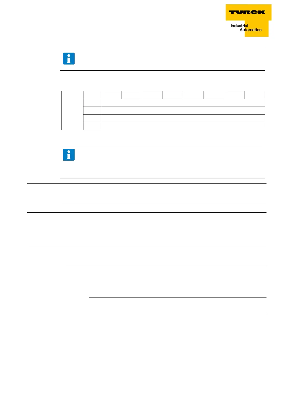
8.3.2 Process data mapping
m = Offset of process output data; depending on extension of station and the corresponding fieldbus.
Process data Meaning
8.3.3 Diagnostic and status messages
LED status displays
NOTE
Negative values are automatically displayed as 0 V in a configured measurement range of 0
to 10 V.
Data Byte Bit 7 Bit 6 Bit 5 Bit 4 Bit 3 Bit 2 Bit 1 Bit 0
Output
m
AO0 LSB
m + 1 AO0 MSB
m + 2 AO1 LSB
m + 3 AO1 LSB
NOTE
With PROFIBUS, PROFINET and CANopen, the I/O data of this module is localized within the
proce
ss data of the whole station via the hardware configuration tool of the fieldbus master.
For DeviceNet, EtherNet/IP and Modbus TCP a detailed mapping table can be created with
the TURCK configuration tool I/O-ASSISTANT V3 (PACTware + BL67-DTM).
Table 8-7:
Process data bits
AOx LSB low byte of the analog value
AOx LSB high byte of the analog value
Table 8-8:
LED status dis-
plays
LED Display Meaning Remedy
D Red Module bus communication
failure
Check if more than two
ad-joining
electronics modules have been
pulled. This concerns modules
located between this module and
the gateway.
OFF No error messages or diagnos-
tics
–