Digital input modules
D300529 0115 - BL67 I/O modules5-30
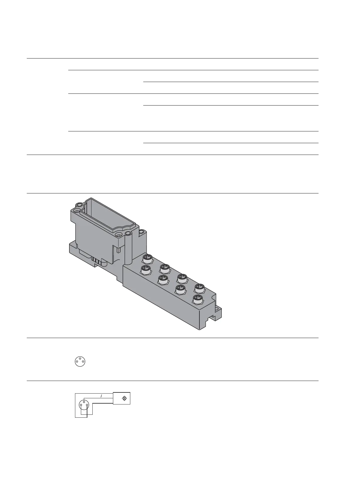
5.5.5 Base modules/pin assignment
BL67-B-8M8
Figure 5-38:
Figure 5-39:
3
1
4
v
1 = V
SENS
3 = GND
4 = Input A
Figure 5-40:
Table 5-31:
Module parame-
ters
A default
setting
Parameter name Value Meaning
Activate input filter 0 =no
A input filter: 0.25 ms
1 = yes input filter: 2.5 ms
Invert digital input 0 =no
A Input signal not inverted.
1 = yes Input signal inverted.
conversion of the effective signal direction for sen-
sors
Activate wire break monitor-
ing
0 =no
A
1 = yes Groupwise wire break monitoring
BL67-B-8M8
Pin assignment
B
L67-8DI-PD with
BL67-B-8M8
Wiring diagram
B
L67-8DI-PD with
BL67-B-8M8