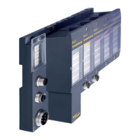
Analog combi modules
D300529 0115 - BL67 I/O modules10-6
10.1.3 Diagnostic and status messages
LED status displays
Diagnostic data
This module has the following diagnostic data available per channel
Bit 7 Bit 6 Bit 5 Bit 4 Bit 3 Bit 2 Bit 1 Bit 0
:
Diagnostics Meaning
Table 10-3:
LED status dis-
plays
LED Display Meaning Remedy
D red, flashing,
0.5
Hz
Diagnostics pending -
Red Module bus communication
failure
Check if more than two ad-joining
electronics modules have been
pulled. This concerns modules
located between this module and
the gateway.
OFF No error messages or diagnos-
tics
–
0 to 4 Green Input channel x active -
Green
flashing,
0.5 Hz
Underflow diagnostic at input -
Green, flash-
ing, 4 Hz
Overflow diagnostic at input -
OFF Input channel x inactive
Hardware
failure
---
Overflow/
underflow
- Wire break Measured value/
output value out
of range
Table 10-4:
Diagnostics
Measured value out
of range
Indicates an over- or undercurrent of 1 % of the set current range; whereby,
undercurrents can only be recognized with those modules that have a set
current range of 4 to 20 mA.
Output value
out of range
Underrun/overrun of the valid output range (limit values see page 10-27ff.)
Wire break
(only 4-20 mA)
Displays a wire break in the signal line for the operating mode 4 to 20 mA. (I
< 3 m)
Overflow/underflow
(NE 43 only)
The output value lies under or over the set output value and can not be given
out (limit values see page 10-27)
Hardware failure Shows common errors of the module hardware (e.g. CRC-error, calibration
error, …). The return analog value in case of an error is "0".
Module exchange necessary!

 Loading...