D300529 0115 - BL67 I/O modules
12-65
BL67-1CNT/ENC
12.5.2 Count mode
After the release signal, the counter module counts from the load value continuously between the
upper and lower limit.
The release is activated by the rising edge from 0 → 1 of the control bit Gate in the Process output/con-
trol interface.
If the counter counts up and reaches
the upper count limit, it will jump to the lower count limit
when another counter signal is received, and will continue to count without signal loss from this
point.
If the counter counts down an
d reaches the lower count limit, it will jump to the upper count limit
when another counter signal is received, and will continue to count without signal loss from this
point.
Limit values of count mode
The limit values have to be defined via the registers no. 36 REG_LOWER_LIMIT and no. 40 REG_UP-
PER_LIMIT in the Register bank of the module (page 12-92).
Maximum count ranges:
The upper count limit is +2 147 483 647 (2
31
-1) = 0×7FFFFFFF
The lower count limit is -2 147 483 648 (-2
31
) = 0×80000000
Signal evaluation A, B, Z
Pulse and direction, single
Pulse and direction, double
Encoder, single
Encoder, double
Encoder, quadruple
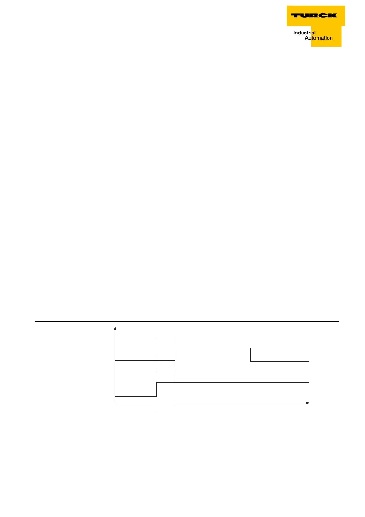
Time between direction signal (B) and coun
ter signal (A)
On pulse generators with a direction signal, it must be ensured that there is a gap of at least 2 μs/200
μs betw
een the direction signal (B) and the counter signal (A), depending on the input filter configured.
Figure 12-33:
signal A
2 µs / 200 µs
signal B
(direction)
time
Time between
direction signal
and counter sig-
nal