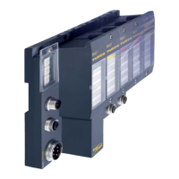
Technology modules
D300529 0115 - BL67 I/O modules12-68
Prerequisites
Parameter Measurement mode = 0
Register no. 52 REG_SCALE_MUL ≠ 1
Register no. 56 REG_SCALE_DIV ≠ 1
Revolutions speed in higher resolution
In order to display a higher-resolved revolutions speed, e.g. 10
-3
/min,
the multiplier has to be multiplied with e.g. 10
-3
.
nf
Multiplikator
1000×
Divisor
-------------------------------------------------
×=
12.5.4 Functions and explanations
Software gate and hardware gate
A release signal is required in order to start counting/measuring.
The counter module controls the starting and stopping of the counting/measuring operation by means
of so
-called "gates". A software gate and a hardware gate are provided for implementing this control
both via the software (process output/control interface) and via a physical output.
Software gate
The release is activated by the rising edge from 0 → 1 of the control bit Gate in the Process output/
control interface.
Resetting this control bit 1 → 0 stops the measurement.
It is always necessary to release the counter via the software-gate. If not, the operation will not be
started
.
If the release is to be initiated on
ly via the software-gate, the parameter Gate function has to be set
in parameter byte 3, bits 0 to 2 (see Module parameters, page 12-85).
Additionally, the counter release can be controlled via a hardware-gate (see below).
Hardware gate
The release is initiated via a high-signa
l (depends on the set threshold) at input Z or via a 24 V-signal
at one of the digital inputs DI0 to DI3.
The release is initiated with a rising edge 0 → 1 at the input an reset with a falling edge 1 → 0.
The parameterization of the digital inputs DI0 to DI3 as hardw
are-gate is also done via the parame-
ter Gate function, parameter byt
e 3, bits 0 to 2 (see Module parameters, page 12-85).
A release via the hardware-gate is thus only possible if, at t
he same time, the control bit "Gate" in the
control interface is set to 1 (software-gate, see above).

 Loading...