D300529 0115 - BL67 I/O modules
12-67
BL67-1CNT/ENC
Period duration measurement
Definition
In this operating mode the counter
module measures the precise time between two rising edges of the
counter signal in μs.
Prerequisites
Parameter Measurement mode = 1
Register no. 52 REG_SCALE_MUL = 1
Register no. 56 REG_SCALE_DIV = 1
The period duration value can be read out from register no. 48 REG_MEASURED_ VALUE and, if param-
eterized, from the Process input/status interface (bytes 8 to 11).
NOTE
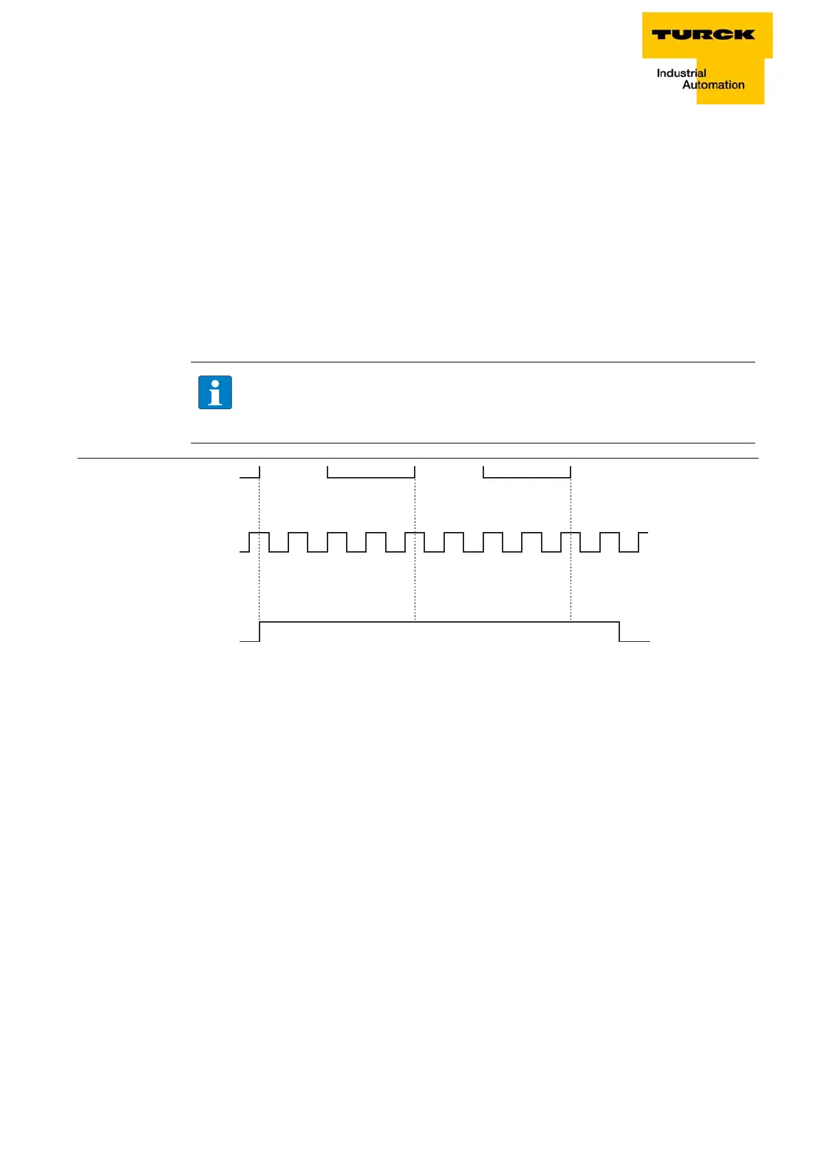
Figure 12-35:
count signal
reference
frequency
period
internal
release
period
start of
period duration
measurement
actualization
of display
end of
period duration
measurement
Revolutions speed measurement
The revolutions measurement is not executed directly.
In the operation mode frequency measurement (see parameter Measurement mode), the no. of revo-
lutions (n) in 1/min can be calculated on
the basis of the frequency (f).
The following applies:
The frequency (f) is provided by the module.
The conversion to the no. of revolutions is done in
ternally by the module using the following for-
mula in consideration of the encoder’s resolution
(pulses/revolution):
nf
Multiplikator
Divisor
-------------------------------
× f
60
1000 Impulse×
-------------------------------------
×==
The multiplier and the divisor are module registers,
which have to be written according to the for-
mula mentioned above.
Multiplier: REG_SCALE_MUL; reg.-no. 52 (page 12-92)
Divisor: REG_SCALE_DIV; reg.-no. 56 (page 12-92)
Register REG_MEASURED_VALUE contains the revolutions speed.
The value displayed in bytes 8 to 11 of the feedback interface (process output) is defined
via parameter REG_AUX_ADR (parameter byte 14).
Here, enter the register no. of the value to be monitored (see Register bank of the module).
Period duration
measurement;
no. of
periods = 2
 Loading...

