Analog input modules
D300529 0115 - BL67 I/O modules6-10
6.2.3 Diagnostic and status messages
LED status displays
Diagnostic data
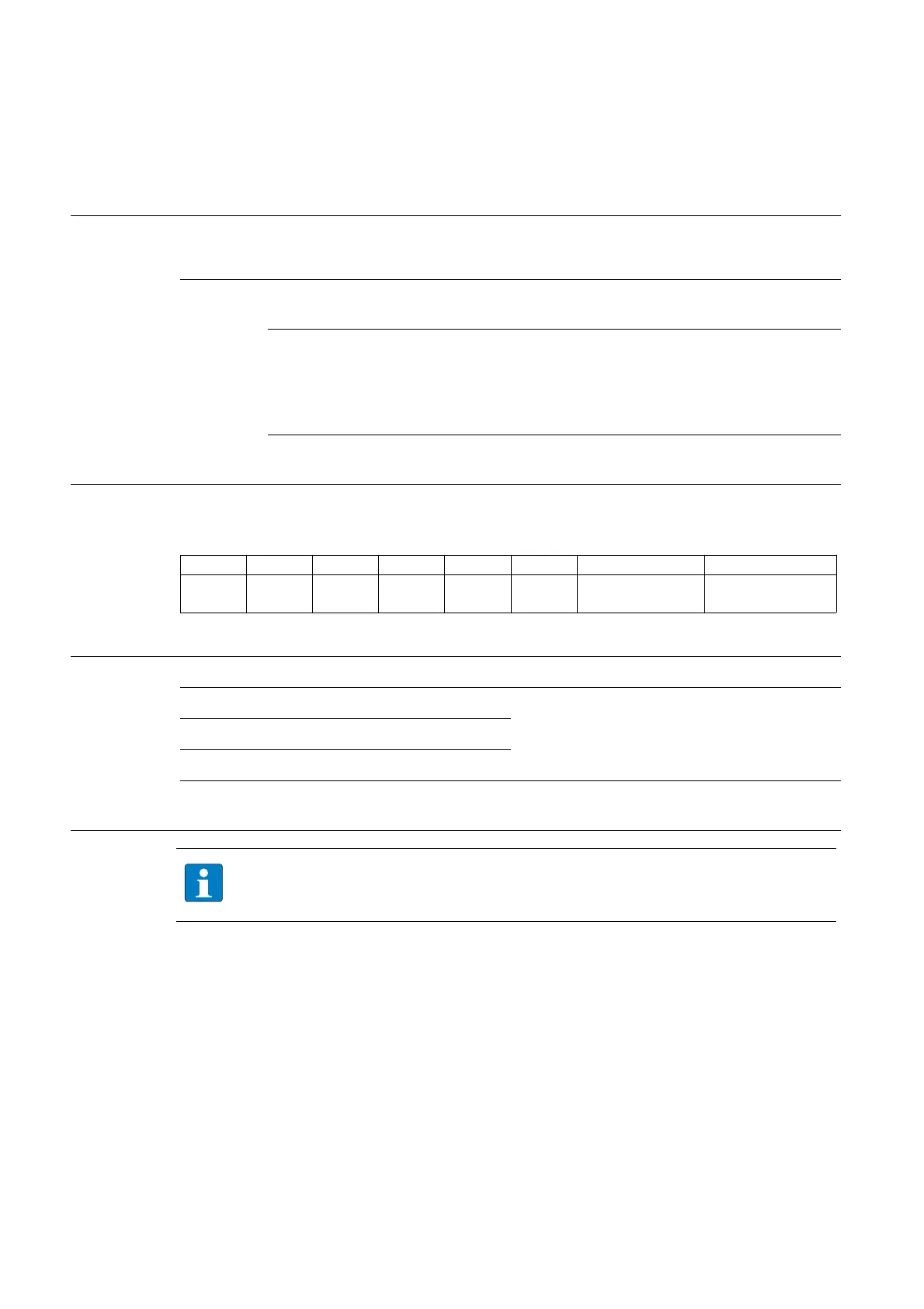
This module has the following diagnostic data per channel
Bit 7 Bit 6 Bit 5 Bit 4 Bit 3 Bit 2 Bit 1 Bit 0
:
Diagnostics Meaning
NOTE
Table 6-4:
LED status dis-
plays
LED Display Meaning Remedy
D red, flashing,
0.5 Hz
Diagnostics pending -
Red M
odule bus communication
failure
Check if more than two ad-joining
electronics modules have been
pulled. This concerns modules
located between this module and
the gateway.
OFF No error messages or diagnos-
tics
–
------Wire break Measured value
out o
f ra
nge
Table 6-5:
Diagnostics
Measured value out of range Indicates an over- or undercurrent of 1 % of the
set current range; whereby, undercurrents can
only be recognized with those modules that
have a set current range of 4 to 20 mA.
–Overcurrent I
max
(I > 20,2 mA)
–Undercurrent: I
min
(I < 3,8 mA)
Wire break (I < 3 mA) Displays a wire break in the signal line for the
operating mode 4 to 20 mA.
In the 12-bit-representation (left-justified) the diagnostic data are transmitted with the lower
nibble of the process data for the respective channel.