Digital input modules
D300529 0115 - BL67 I/O modules5-28
5.5.3 Diagnostic and status messages
LED status displays
Diagnostic data
This module has the following diagnostic data available
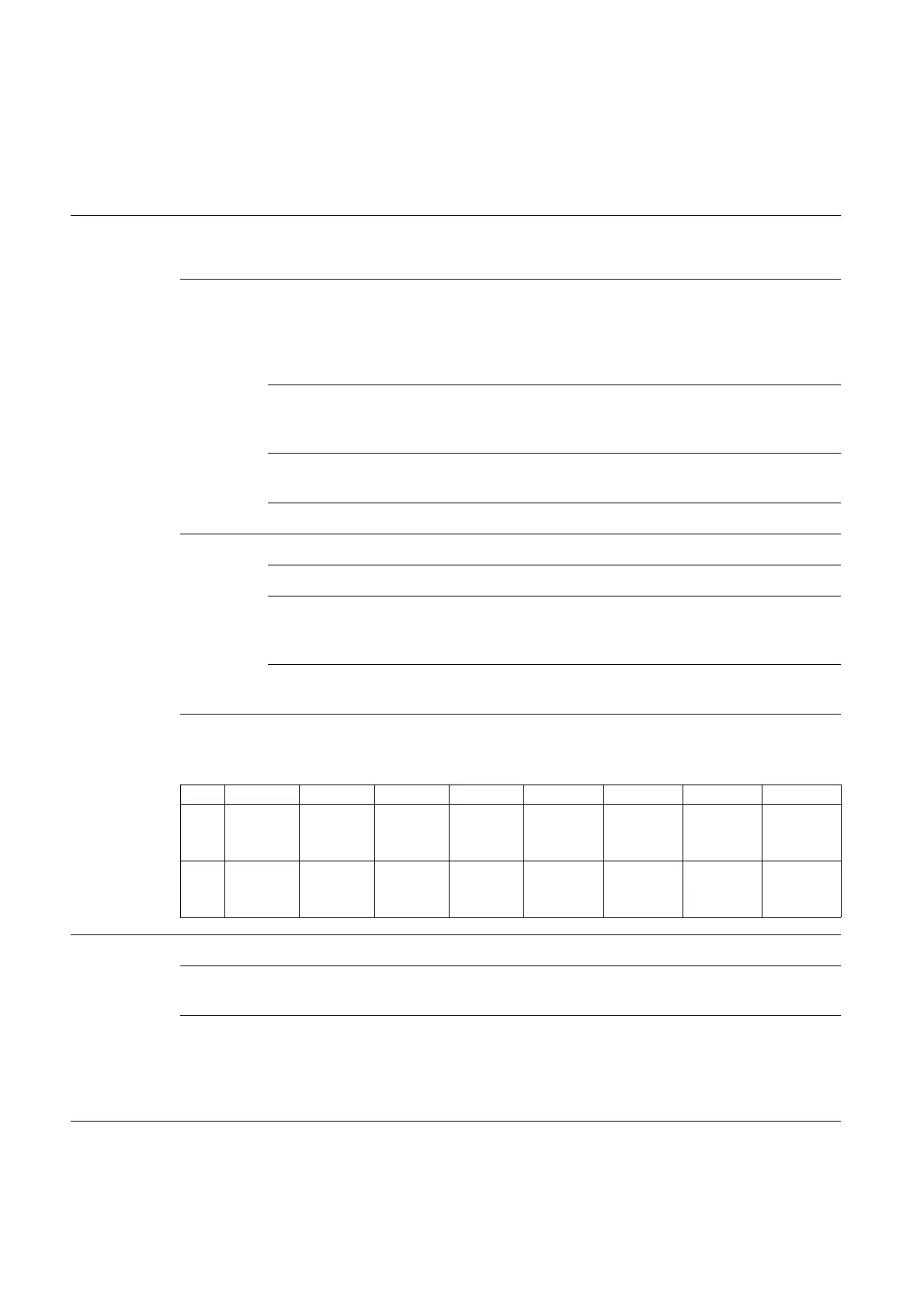
Byte Bit 7 Bit 6 Bit 5 Bit 4 Bit 3 Bit 2 Bit 1 Bit 0
Diagnostics
:
Table 5-29:
LED status dis-
plays
LED Display Meaning Remedy
D Red Module bus communication
failure
C
heck if more than two ad-joining
electronics modules have been
pulled. This concerns modules
located between this module and
the gateway.
Red No field voltage
(LED V
I
at Power Feeding
module is "off")
Check the power supply for the
inputs (V
sens
).
Red,
flashing, 0.5 Hz
Diagnosis pending -
OFF No error messages –
0 to 7 Green Status of channel x = "1" –
OFF Status of channel x = "0" -
Red
flashing, 2 Hz
LED 0 to 7:
Overload sensor supply channel
x
Check the sensor supply.
Red LED 0 to 3:
open-circuit monitoring
Check the wires for open-circuits.
0 - - - - Overcurr.
sensor
supply D
Ov
ercurr.
sensor
supply C
Overcurr.
sensor
supply B
Overcurr.
sensor
supply A
1- - - - Wire
break ch 3
and 7
Wire
break
ch 2 and 6
Wire
break ch 1
and 5
Wire
break ch 0
and 4
Table 5-30:
Diagnostics
Overcurrent sensor supply Overcurrent (short circuit) or wire break at the
sensor supply A, B, C or D (see Table 5-35)
Wire break Groupwise wire break detection:
Group A (channel 0 and 4)
Group B (channel 1 and 5)
Group C (channel 2 and 6)
Group D (channel 3 and 7)