Relay modules
D300529 0115 - BL67 I/O modules11-2
11.1 General
BL67 relay modules (R) receive output values from the gateway via the internal module bus. The mod-
ules convert these values and transmit the correspondin
g circuit state for each channel to the field level
via the base modules.
Relay modules are suitable for solenoid valves, DC contactors and signal lamps in the nominal-load
vo
ltage range 24 V DC/V AC to 230 V AC. Relay modules have a reverse polarity protection and are
potentially isolated from the power supply.
LED status indicators
Error signals from the I/O level are indicated by each module via
the "D" LED. The corresponding diag-
nostic information is transmitted to
the gateway via diagnostic bits. If the "D" LED lights up continu-
ously red, it signals the failure of
the module bus communication of the relay modules.
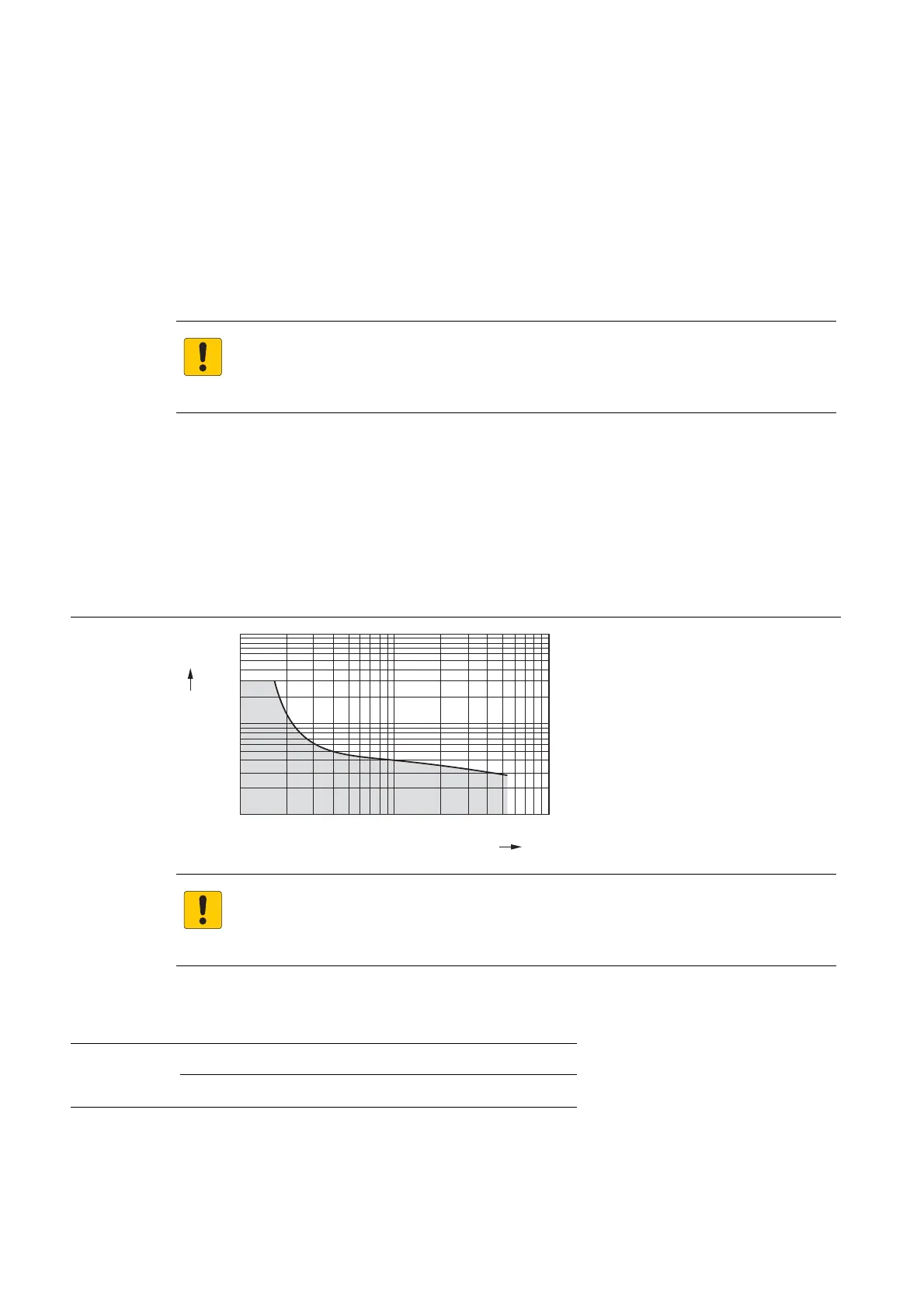
11.1.1 Load limit curve with resistive load
At 1 000 switching cycles, no sustained arcs with a burning life > 10 ms may occur.
Figure 11-1:
11.1.2 Module overview
ATTENTION!
Electric arc when switching inductive loa
ds
Destruction of contacts
Provide an external suppressor.
Definition of load
limit curve
ATTENTION!
Switching of too high loads/power
Dest
ruction of contacts
Observe the devices' load limit curve.
Table 11-1:
Overview
Relay modules
BL67-8DO-R-NO normally open contact