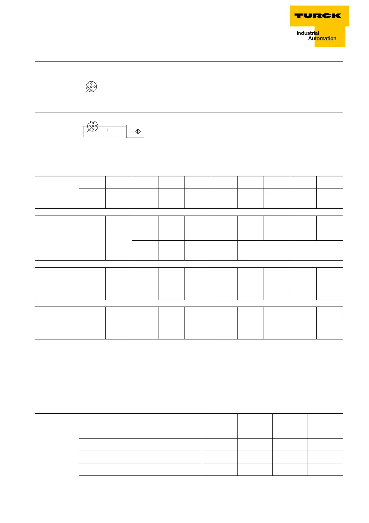
Figure 5-24:
4
1
3
2
5
v
1 = V
SENS
2 = n.c.
3 = GND
4 = Input A
5 = PE
Figure 5-25:
5
1 (+) BN
3 () BU
4 ( ) BK
D300529 0115 - BL67 I/O modules
5-19
BL67-4DI-PD
5.3.6 Signal assignment
n = process data offset in input data; depending on
extension of station and the corresponding fieldbus
C = slot no.
P = pin no.
5.3.7 sensor supply
Pin assignment
BL67-4DI-PD with
BL67-B-4M12
Wiring diagram
B
L67-4DI-PD with
BL67-B-4M12
Table 5-15:
Signal assign-
ment
with BL67-B-
4M8
ByteBit 7Bit 6Bit 5Bit 4Bit 3Bit 2Bit 1Bit 0
In n - - - - C3P4 C2P4 C1P4 C0P4
Table 5-16:
Signal assign-
ment with BL67-B-
2M12 incl. wire
break detection
ByteBit 7Bit 6Bit 5Bit 4Bit 3Bit 2Bit 1Bit 0
In n - - - - C1P2 C0P2 C1P4 C0P4
- - - - Wire break
1 + 2
Sensor signal
1 + 2
Table 5-17:
Signal assign-
ment with
BL67-B-2M12-P
ByteBit 7Bit 6Bit 5Bit 4Bit 3Bit 2Bit 1Bit 0
In n - - - - C1P2 C1P4 C0P2 C0P4
Table 5-18:
Signal assign-
ment with
BL67-B-4M12
ByteBit 7Bit 6Bit 5Bit 4Bit 3Bit 2Bit 1Bit 0
In n - - - - C3P4 C2P4 C1P4 C0P4
Table 5-19:
sensor supply
V
sens
ABCD
BL67-B-2M12 C0P1 C1P1 - -
BL67-B-2M12-P C0P1 C1P1 - -
BL67-B-4M12 C0P1 C1P1 C2P1 C3P1
BL67-B-4M8 C0P1 C1P1 C2P1 C3P1