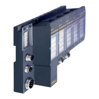
Technology modules
D300529 0115 - BL67 I/O modules12-88
Function DO3 0 = output A The output is used as digital out-
put.
1 = encoder power supply
The output is used as power
supply for the connected
encoder.
Function DI3 0 = input A The input is used as digital
input.
1 = encoder-GND
The input is used as encoder-
GND.
PullUp Z 0 = 0 A The PullUp-resistance for input
Z is switched-off.
1 = on
The PullUp-resistance for input
Z is switched-on.
Threshold input A, B, Z 0000 = 1 V
0001 = 1.5 V
0010 = 2 V
0011 = 2.5 V
0100 = 3 V
0101 = 4 V
0110 = 5 V
0111 = 6 V
1000 = 7 V
1001 = 8 V
1010 = 9 V
1011 = 10 V
A
1100 = 12 V
1101 = 14 V
1110 = 16 V
1111 = 18 V
Setting the threshold value for
the inputs A, B and Z.
Counter mode 0 = encoder A Operation mode for the connec-
tion of an incremental encoder.
1 = pulse and direction
Operation mode for the connec-
tion of a counter with pulse- and
direction-input.
Measurement mode 0 = frequency measurement A Setting the measurement mode
1 = period duration measure-
ment
Gate 0 =no A Gate not inverted
1 = yes
Gate inverted
Table 12-12:
Parameters of the
BL67-1CNT/ENC
Parameter name Value Meaning

 Loading...