Analog output modules
D300529 0115 - BL67 I/O modules8-26
.
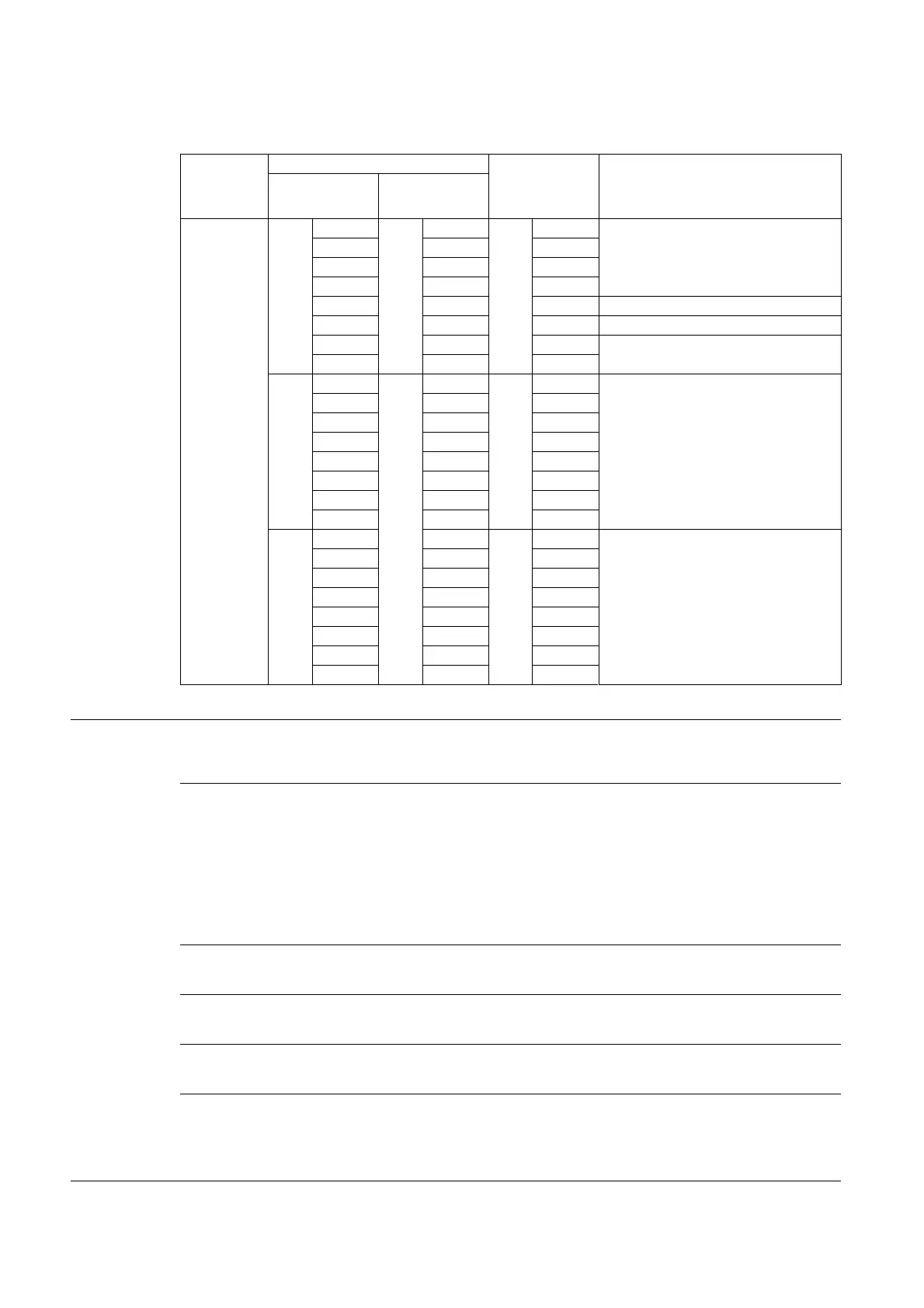
Parameter settings
Channel 3
Byte 9
Bit 0
Word 4
Bit 8
Byte 9
Bit 0 Operation mode
Bit 1 Bit 9 Bit 1
Bit 2 Bit 10 Bit 2
Bit 3 Bit 11 Bit 3
Bit 4 Bit 12 Bit 4 Data format
Bit 5 Bit 13 Bit 5 Deactivate diagnostics
Bit 6 Bit 14 Bit 6 Output on module bus error
Bit 7 Bit 15 Bit 7
Byte 10
Bit 0
Word 5
Bit 0
Byte 11
Bit 0 Substitute value (low byte)
Bit 1 Bit 1 Bit 1
Bit 2 Bit 2 Bit 2
Bit 3 Bit 3 Bit 3
Bit 4 Bit 4 Bit 4
Bit 5 Bit 5 Bit 5
Bit 6 Bit 6 Bit 6
Bit 7 Bit 7 Bit 7
Byte 11
Bit 0 Bit 8
Byte 10
Bit 0 Substitute value (high byte)
Bit 1 Bit 9 Bit 1
Bit 2 Bit 10 Bit 2
Bit 3 Bit 11 Bit 3
Bit 4 Bit 12 Bit 4
Bit 5 Bit 13 Bit 5
Bit 6 Bit 14 Bit 6
Bit 7 Bit 15 Bit 7
Table 9:
Module parame-
te
rs
A default
settings
Operation mode 0000 = voltage -10 … 10 V DC standard A
0001 = voltage 0 … 10 V DC standard
0010 = voltage -10 … 10 V DC PA (NE 43)
0011 = voltage 0 … 10 V DC PA (NE 43)
0100 = voltage -10 … 10 V DC extended range
0101 = voltage 0 … 10 V DC extended range
1111 = deactivate
Data format 0 = 15 bit + sign
A
1 = 12 bit (left-justified)
Deactivate diagnostics 0 = no
A
1 = yes
Output on module bus erro
r 0 = substitute value A
1 = current value
Substitute value Substitute value = "0"
A
The substitute value will be transmitted if the respective parame-
ters of the gateway have been set to "output substitute value" or if
the communication between module and gateway is disturbed.
Standard
PROFIBU
S
PROFINET
Parameter
byte-
oriented
word-
oriented