NOTE
Parameter settings
Analog combi modules
D3
00529 0115 - BL67 I/O modules10-10
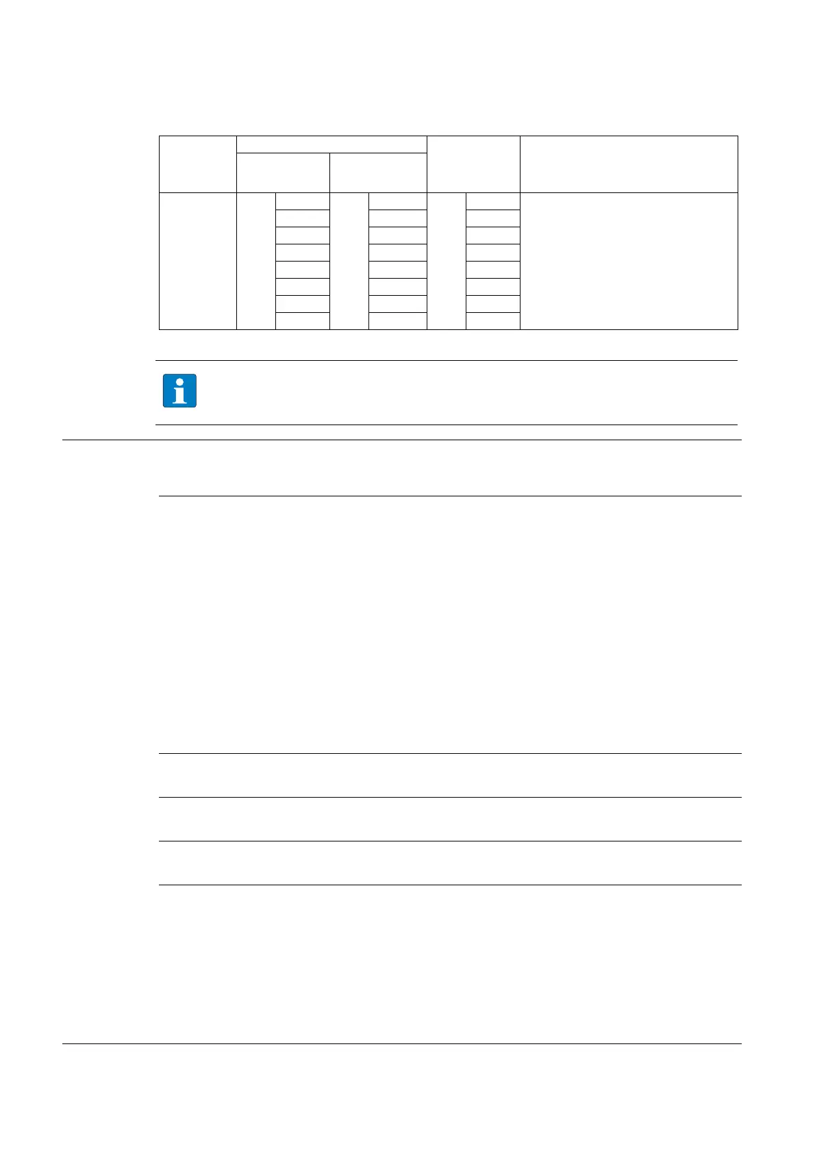
Output 3
Byte 15
Bit 0
Word 7
Bit 8
Byte 14
Bit 0 Substitute value (high byte)
Bit 1 Bit 9 Bit 1
Bit 2 Bit 10 Bit 2
Bit 3 Bit 11 Bit 3
Bit 4 Bit 12 Bit 4
Bit 5 Bit 13 Bit 5
Bit 6 Bit 14 Bit 6
Bit 7 Bit 15 Bit 7
Concerning the "number representation", please observe the tables for measurement value
representation on the following pages.
Table 11:
Module parame-
te
rs
A default
settings
B for in- and out-
puts
C only for
inputs
Operation mode 0000 = voltage, -10 … 10 VDC standard A, B
0001 = voltage, 0 … 10 VDC standard B
0010 = voltage, -10 … 10 VDC PA (NE 43) B
0011 = voltage, 0 … 10 VDC PA (NE 43) B
0100 = voltage, -10 … 10 VDC ext. range B
0101 = voltage, 0 … 10 VDC ext. range B
0110 = reserved
0111 = reserved
1000 = 0 … 20 mA standard A, C
1001 = 4 … 20 mA standard C
1010 = 0 … 20 mA PA (NE 43) C
1011 = 4 … 20 mA PA (NE 43) C
1100 = 0 … 20 mA ext. range C
1101 = 4 … 20 mA ext. range C
1111 = deactivate
Data format 0 = 15 bit + sign
A
1 = 12 bit (left-justified)
Deactivate diagnostics 0 =no
A
1 = yes
Output on module bus error 0 = substitute value
A
1 = current value
Substitute value Ax Substitute value = "0"
A
1. The substitute value defined here will be sent in consequence of
certain events parameterized in the gateway.
or
2. In case of a module bus error: The substitute value defined here
will be sent if the parameter "Behavior module bus error Ax" is set
to "output substitute value".
Standard
PROFIBUS/
PROFIN
ET
Parameter
byte-
oriented
word-
oriented