UTT Technologies Hardware Installation
http://www.uttglobal.com Page 4
Chapter 1. Hardware Installation
This chapter describes the physical characteristics of the Device and explains how to install them.
1.1 Panel Description
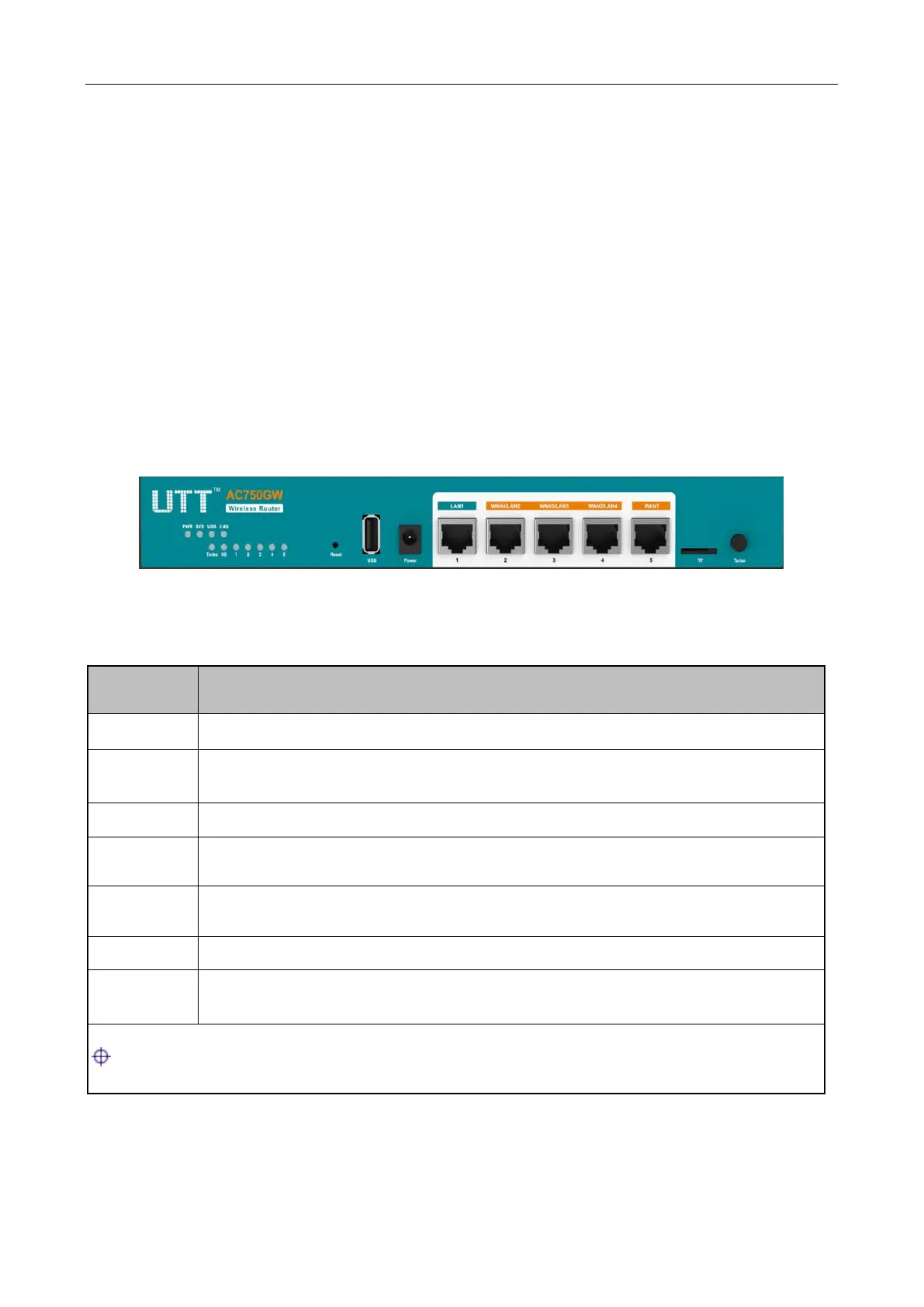
1) Front Panel
The LED indicators, the interface and the button are located on the front panel of the Device, here
we use AC750GW as an example, as for other models, please see the product.
Figure 1-1 Front Panel_AC750GW
PWR The Power LED indicator is on when the Device is powered on.
SYS
The LED indicator blinks twice per second when the system is working properly,
and it will blink slower under heavy load.
USB The LED indicator is on when the USB interface is connected properly.
2.4G
The 2.4G LED indicator is on when 2.4GHZ Wireless is enabled, and it blinks
when transmitting/receiving 2.4G wireless data.
5G
The 5G LED indicator is on when 5GHZ Wireless is enabled, and it blinks when
transmitting/receiving 5G wireless data.
Turbo The Turbo LED indicator blinks when the function is enabled.
1,2,3,4,5
The LAN LED indicator is on when Ethernet cable connection is normal, and it
blinks when the LAN port is sending or receiving data.
: The number of port status LEDs depends on the Device model.
Table 1-1 LED Description