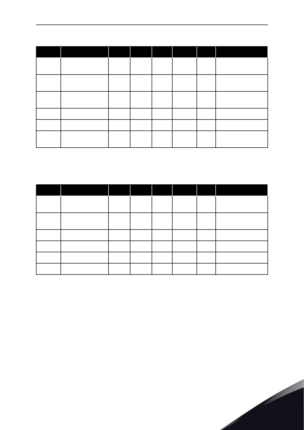
Table 44: Analogue input 1 settings
Index Parameter Min Max Unit Default ID Description
P3.5.2.1.1 AI1 Signal Selection
AnIN
SlotA.1 *
377
P3.5.2.1.2
AI1 Signal Filter
Time
0.00 300.00 s 0.1 * 378
P3.5.2.1.3 AI1 Signal Range 0 1 0 * 379
0 = 0…10V / 0…20mA
1 = 2…10V / 4…20mA
P3.5.2.1.4 AI1 Custom. Min -160.00 160.00 % 0.00 * 380
P3.5.2.1.5 AI1 Custom. Max -160.00 160.00 % 100.00 * 381
P3.5.2.1.6 AI1 Signal Inversion 0 1 0 * 387
0 = Normal
1 = Signal inverted
* = The selection of the application with parameter P1.2 Application gives the default value.
See the default values in 12.1 The default values of parameters in the different applications.
Table 45: Analogue input 2 settings
Index Parameter Min Max Unit Default ID Description
P3.5.2.2.1 AI2 Signal Selection
AnIN
SlotA.2 *
388
See P3.5.2.1.1.
P3.5.2.2.2
AI2 Signal Filter
Time
0.00 300.00 s 0.1 * 389
See P3.5.2.1.2.
P3.5.2.2.3 AI2 Signal Range 0 1 1 * 390 See P3.5.2.1.3.
P3.5.2.2.4 AI2 Custom. Min -160.00 160.00 % 0.00 * 391 See P3.5.2.1.4.
P3.5.2.2.5 AI2 Custom. Max -160.00 160.00 % 100.00 * 392 See P3.5.2.1.5.
P3.5.2.2.6 AI2 Signal Inversion 0 1 0 * 398 See P3.5.2.1.6.
* = The selection of the application with parameter P1.2 Application gives the default value.
See the default values in 12.1 The default values of parameters in the different applications.
PARAMETERS MENU VACON · 141
LOCAL CONTACTS: HTTP://DRIVES.DANFOSS.COM/DANFOSS-DRIVES/LOCAL-CONTACTS/
5

 Loading...