aXSU,R=[R],I=[I],S=[S],H=[Y]<cr><lf>
8.1.4.2 Setting Fields
Parameter Description
[R] Parameter selection: This field consists of 16 bits
defining
the supervisor parameters included in the
data messages. The bit value 0 disables and the bit
value 1 enables the parameter.
Bits 1-8 determine the parameters included in the message obtained with the following
commands:
•
ASCII: aR5 and ar5
• NMEA 0183: $--WIQ,XDR*hh
• SDI-12: aM5, aMC5, aC5, and aCC5
• SDI-12 continuous: aR5 and aRC5
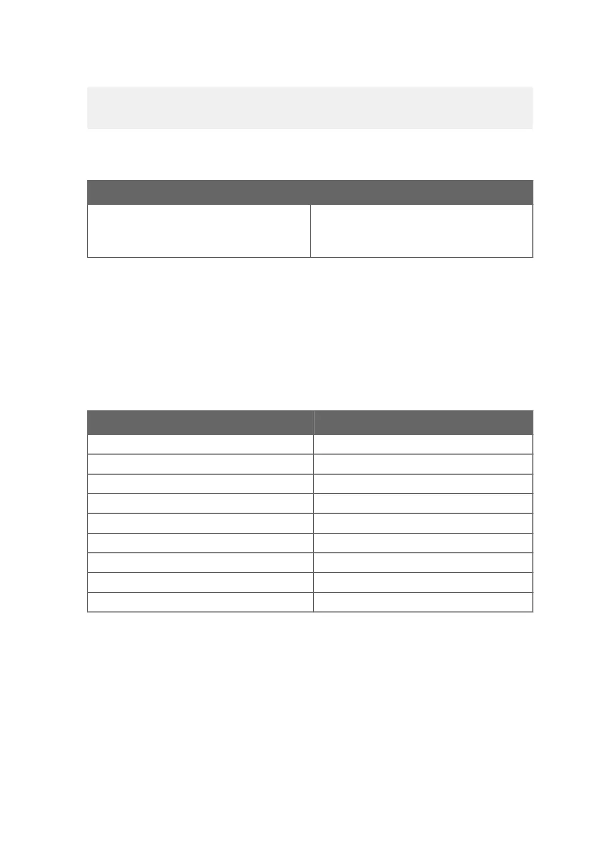
Table 27 Supervisor Parameters Bits 1-8
Bit Description
1st bit (most left) Th Heating temperature
2nd bit Vh Heating voltage
3rd bit Vs Supply voltage
4th bit Vr 3.5 V reference voltage
5th bit Id Information field
6th bit spare
7th bit spare
8th bit spare
& delimiter
Bits 9-16 determine the supervisor parameters included in the composite data message
obtained with the follo
wing commands:
• ASCII: aR0 and ar0
• NMEA 0183: aR0and ar0
• SDI-12: aM, aMC, aC, and aCC
• SDI-12 continuous: aR and aRC
Chapter 8 – Sensor and Data Message Settings
133
sales@streamlinemeasurement.co.uk
www.streamlinemeasurement.co.uk

 Loading...


