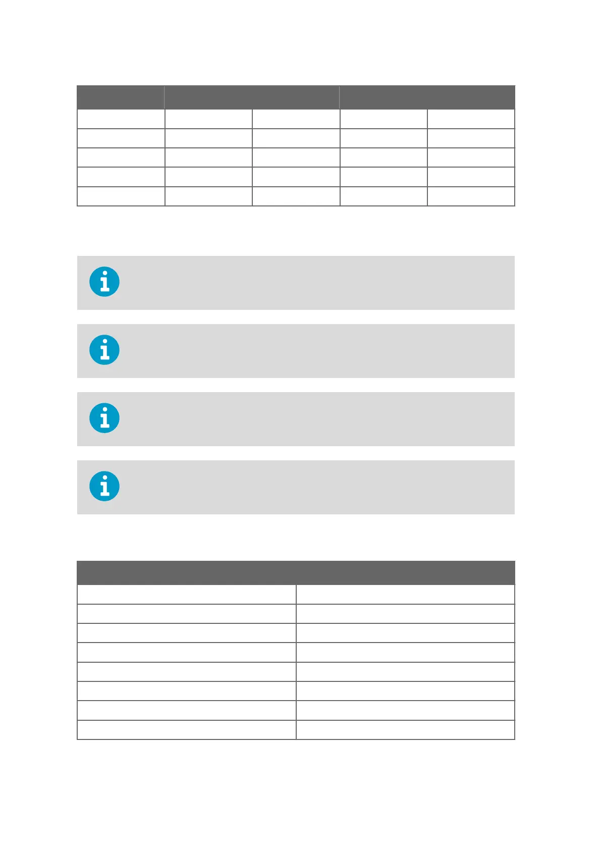
Screw terminal RS-232 SDI-12 RS-485 RS-422
5 TX- Data out (TxD) Data out (Tx) Data - Data out (TX+)
4 RX+ - - - Data in (Rx+)
3 RX- - - - Data in (Rx-)
2 VIN- Vin- (operating) Vin- (operating) Vin- (operating) Vin- (operating)
1 VIN+ Vin+ (operating) Vin+ (operating) Vin+ (operating) Vin+ (operating)
The signal names Data in (RxD) and Data out (TxD) in the table describe the direction of
data
flow as seen from the transmitter.
Ground the external wiring shield. The shield is not connected inside WXT.
In true SDI-12, Data in (Rx) and Data out (Tx) lines must be combined.
Short circuit loops are required between terminals 3 & 5, and 4 & 6 for RS-485. See 5.
3.2
Internal Wiring (page 61).
Do not use operating power supply ground (VIN-) for communication (RS-232, RS-485,
SDI-12, RS-4
22). Use SGND communication ground (GND).
Table 8 WXT532 mA Output Option Screw Terminal Pin-outs
Screw terminal mA Output
10 HTG- Vh- (heating)
9 HTG+ Vh+ (heating)
8 GND2 GND Iout2
7 Iout2 Iout2 (direction)
6 GND1 GND Iout1
5 Iout1 Iout1 (wind)
4 NC -
3 NC -
WXT530 Series User Guide M211840EN-D
60
sales@streamlinemeasurement.co.uk
www.streamlinemeasurement.co.uk

 Loading...


