2. Pull out the bottom part of the transmitter.
3. Insert the po
wer supply wires and signal wires through the cable gland(s) in the bottom
of the transmitter. Cable glands are included in the optional Bushing and Grounding Kit
(222109).
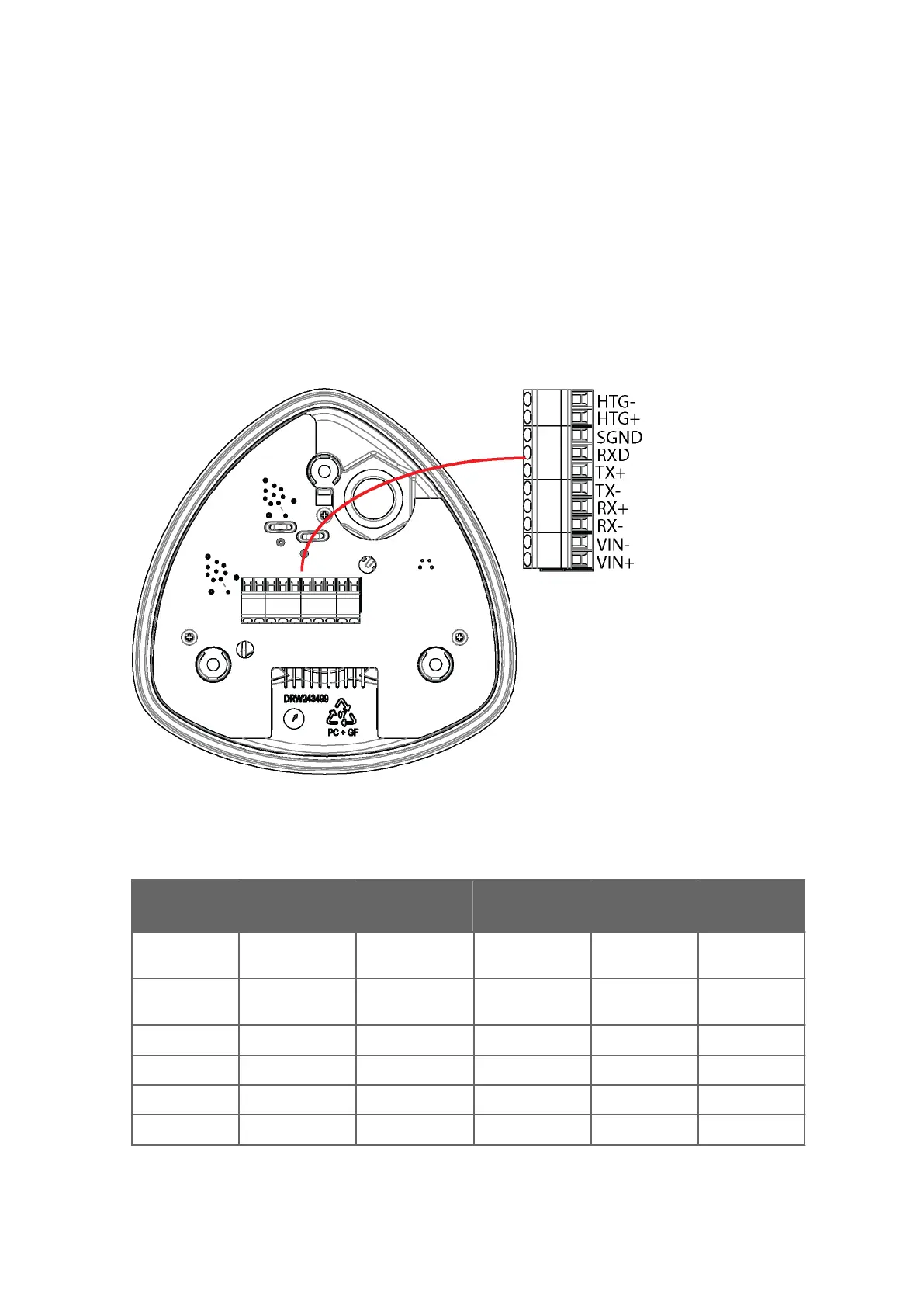
4. Connect the wires as shown in the following table.
5. Replace the bottom part and tighten the three screws. Make sure that the flat cable
does not get squeezed or stuck between the top and the funnel for the flat cable and it
is properly connected. To make sure that the radiation shield stays straight, do not
tighten the screws all the way in one go. Do not overtighten.
Figure 28 Screw Terminal Block
Table 14 Screw Terminal Pin-outs for Serial Interfaces and Power Supplies
Screw
T
erminal PIN
RS-
232 SDI-12 RS-485 RS-422 mA Output
1 VIN+ Vin+ (Operating) Vin+ (Operating) Vin+ (Operating) Vin+
(Oper
ating)
Vin+
(Operating)
2 VIN- Vin- (Operating
GND)
V
in- (Operating
GND)
Vin- (Operating
GND)
Vin- Operating
GND)
Vin- (Operating
GND)
3 RX- Data- Data in (RX-)
4 RX+ Data+ Data in (RX+)
5 TX- Data out (TxD) Data in/out (Tx) Data- Data out (TX-) Iout1
6 TX+ Data+ Data out (TX+) GND
Chapter 5 – Wiring and Power Management
65
sales@streamlinemeasurement.co.uk
www.streamlinemeasurement.co.uk

 Loading...


