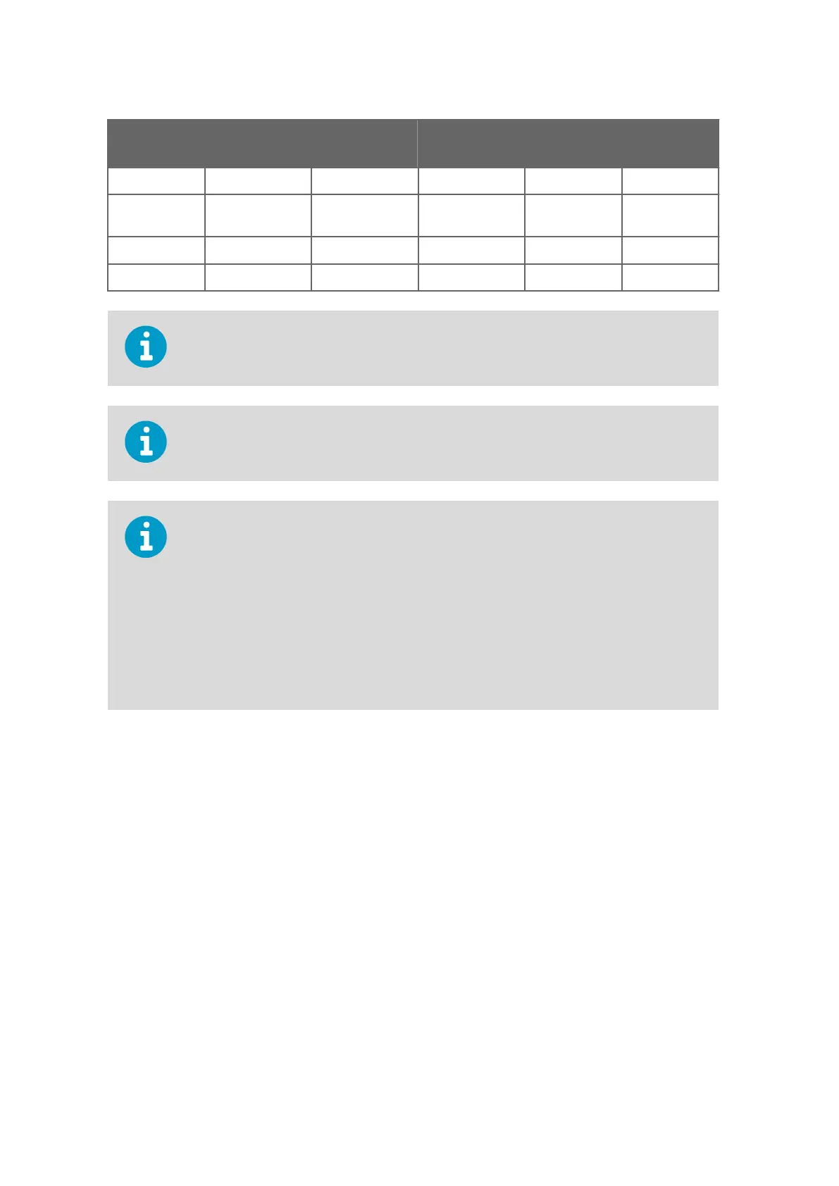
Screw
Terminal PIN
RS-
232 SDI-12 RS-485 RS-422 mA Output
7 RXD Data in (RxD) Data in/out (Rx) Iout2
8 SGND Communication
ground (
GND)
Communication
ground (GND)
Communication
ground (GND)
GND
9 HTG+ Vh+ (Heating) Vh+ (Heating) Vh+ (Heating) Vh+ (Heating) Vh+ (Heating)
10 HTG- Vh- (Heating) Vh- (Heating) Vh- (Heating) Vh- (Heating) Vh- (Heating)
Use a shielded cable and ground the external wiring shield.
For the SDI-12 mode, the Data in/out (Tx) and Data in/out (Rx) signals must be connected
internally by looping pins 5 and 7, or, externally by looping the M12 pins 1 and 7.
If the transmitter was ordered with any other serial communication than RS-422, the
int
ernal wiring has loops between pins 3 and 5, and between 4 and 6. For RS-422
operation, you must remove the loops. For the RS-485 communication mode, short-circuit
loops are required between pins 3-5 and 4-6.
3 = RX Data-, Loop with Blue
4 = RX Data+, Loop with Gray
5 = TX Data-, Blue wire
6 = TX Data+, Gray wire
The transmitter has by default factory-installed loops in all serial communication options
except RS-422.
WXT530 Series User Guide M211840EN-D
66
sales@streamlinemeasurement.co.uk
www.streamlinemeasurement.co.uk

 Loading...


