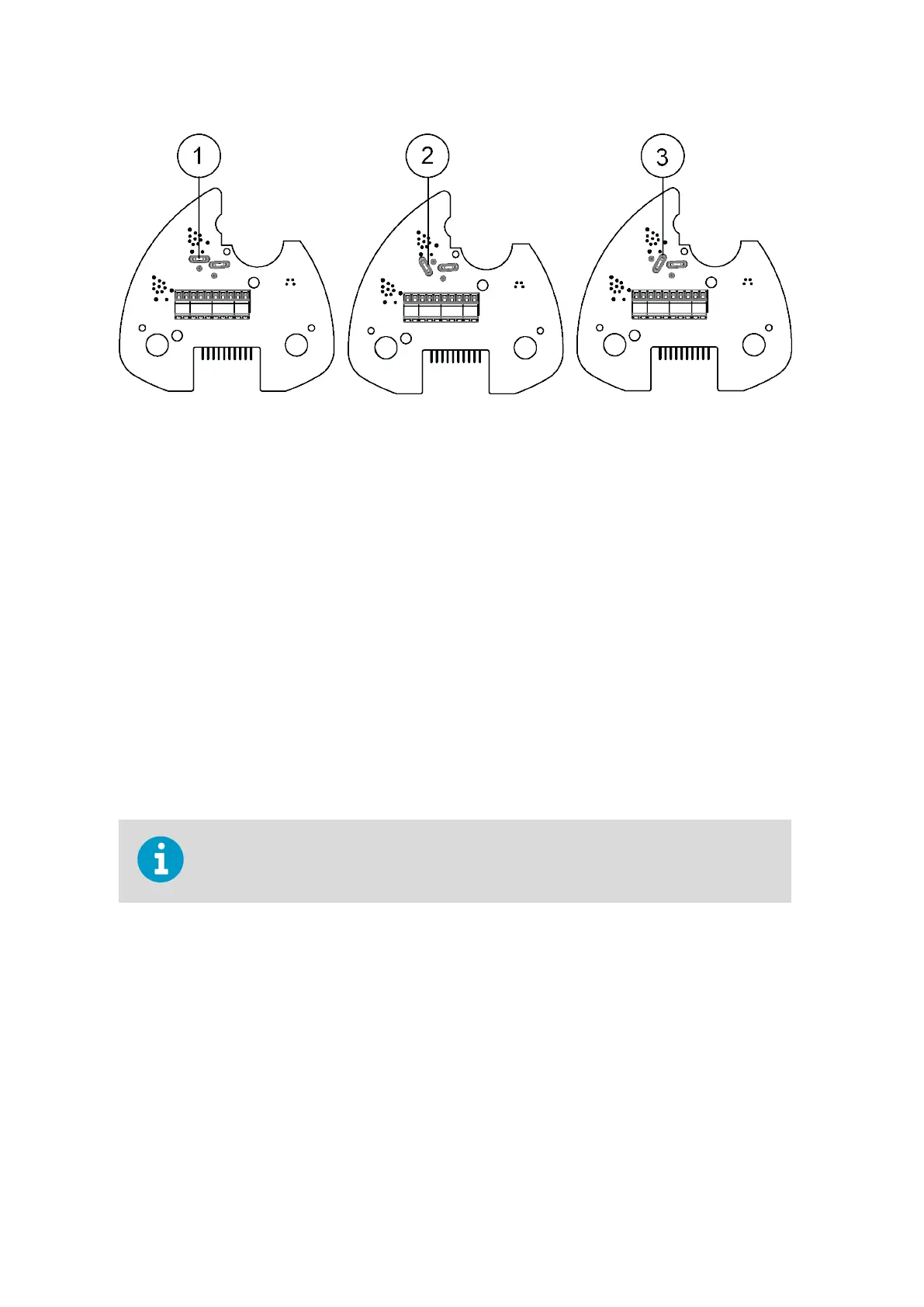
Figure 30 Termination Jumper Positions
1 NC, no termination
2 R, 121 Ω termination
3 RC, 121 Ω series with 4.7 nF capacitor termination
The termination resistors increase power consumption significantly during data
tr
ansmis
sion. If low power consumption is a must, connect a 0.1 uF capacitor in series with
each external termination resistor or use internal RC termination.
Note that the RS-485 interface can be used with four wires (as RS-422).
The main
dierence between the RS-485 and RS-422 interfaces is their protocol:
• In the RS-4
22 mode the transmitter is constantly enabled
• In the RS-485 mode the transmitter is enabled only during transmission (for allowing
the host’s transmission in the two-wire case).
The RS-232 output swings only between 0 ... +4.5 V. This is enough for modern PC inputs.
The recommended maximum for the RS-232 line length is 100 m (300 ft) with 1200 Bd data
rate. Higher rates require shorter distance, for instance, 30 m (100 ft) with 9600 Bd.
If you use the transmitter on an RS-485 bus with other polled devices, always disable the
error mes
saging feature with the command: 0SU,S=N<crlf>.
WXT530 Series User Guide M211840EN-D
68
sales@streamlinemeasurement.co.uk
www.streamlinemeasurement.co.uk

 Loading...


