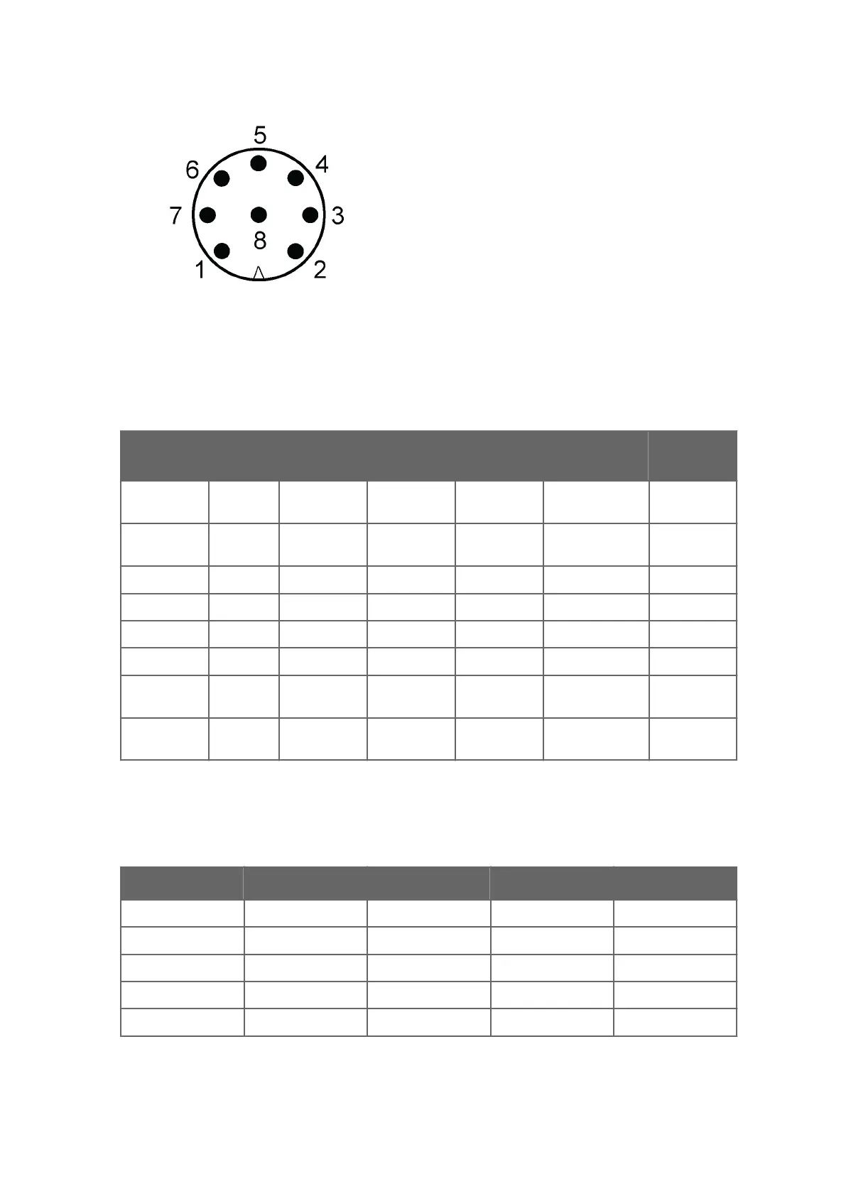
Figure 26 Pins of 8-pin M12 Connector
The following table shows the pin connections for the 8-pin M12 connector and the wire
color
s of the respective M12 cable (optional, 2/10 m).
Table 6 Pin-outs for WXT530 Series Serial Interfaces and Power Supplies
Wire Color M12 Pin#
RS-232
1)
SDI-12
1)
RS-485
1)
RS-422
1)
mA
Output
2)
White 1 Data in (RxD) Data in/out
(Rx)
- Da
ta out (TX-) Iout2
Brown 2 Vin+
(operating)
Vin+
(operating)
Vin+
(operating)
Vin+ (operating) Vin+
(operating)
Green 3 GND for data GND for data GND for data Data out (TX+) GND Iout2
Yellow 4 Vh+ (heating) Vh+ (heating) Vh+ (heating) Vh+ (heating) Vh+ (heating)
Gray 5 - - Data+ Data in (RX+) GND Iout1
Pink 6 Vh- (heating) Vh- (heating) Vh- (heating) Vh- (heating) Vh- (heating)
Blue 7 Data out
(T
xD)
Data in/out
(Tx)
Data- Data in (RX-) Iout1
Red 8 Vin-
(oper
ating)
Vin-
(operating)
Vin-
(operating)
Vin- (operating) Vin-
(operating)
1) Available for all models
2) W
XT532 option
Table 7 Screw Terminal Pin-outs
Screw terminal RS-232 SDI-12 RS-485 RS-422
10 HTG- Vh- (heating) Vh- (heating) Vh- (heating) Vh- (heating)
9 HTG+ Vh+ (heating) Vh+ (heating) Vh+ (heating) Vh+ (heating)
8 SGND GND for data GND for data GND for data GND for data
7 RXD Data in (RxD) Data in (Rx) - -
6 TX+ - - Data+ Data out (TX-)
Chapter 5 – Wiring and Power Management
59
sales@streamlinemeasurement.co.uk
www.streamlinemeasurement.co.uk

 Loading...


