199
S T M R
S
m
D
FNC
65
1
2
M
3
○○○
m
X Y M S
D.b R.b
KnX KnY
KnM KnS
T C
D,R
V,Z
UnG
K,H
E
" $"
S
D
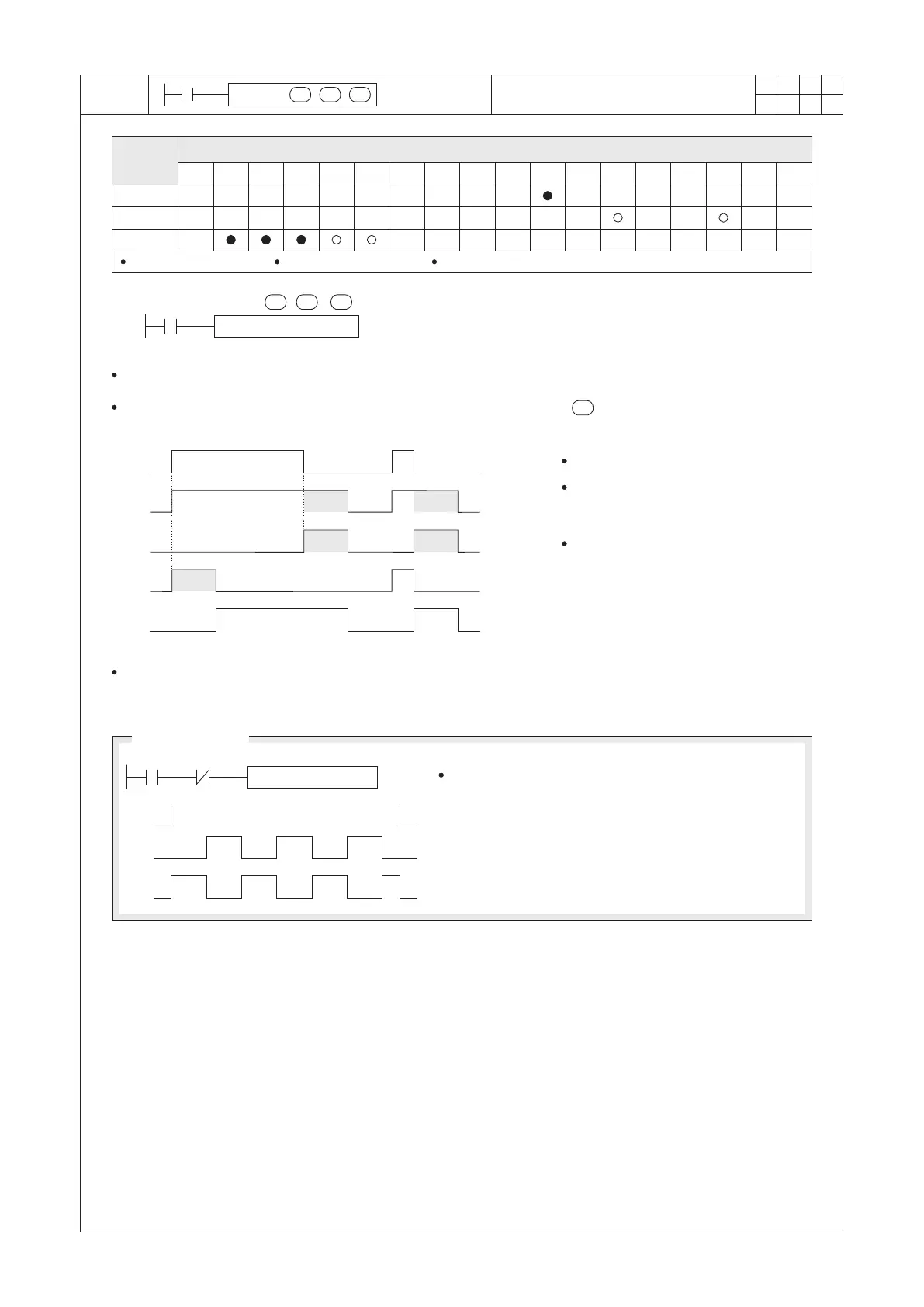
STMR T0 K20 Y20
X20
X20 M3
STMR
K10
T0
M0
X20
M1
M2
X20
Y20
Y21
Y22
Y23
S
m
D
m
○
Operand
Devices
Special Timer
S=T0~T199
m=1~32,767
D occupies 4 components
S : the ID number of designated Timer
D : the head ID number of the output device
m : the setting value of the Timer (unit=100ms)
The STMR instruction is operated exclusively to produce the OFF-delay, the delay trigger and a flashing circuit.
When X20= “ON”, the STMR instruction starts to be performed. Since the =20, the T0 become a 2 seconds
setting value Timer.
2 Sec. 2 Sec.
2 Sec. 2 Sec.
2 Sec.
The Y20 is an OFF-delay output.
The Y21 will have one delay output
when that input signal turned from
“ON” to “OFF”.
The Y22 and Y23 are designed for
output signals those are exclusively to
compose the flashing circuit. The
following example is an applied method
for the flashing circuit.
In the program, do not reuse the Timer ID number which has been used by this instruction.
Perform a serial link “b” contact of M3 after X20,
then the M1 and M2 will perform the flashing circuit.
Flashing Circuit
1
Sec.
1
Sec.