SHB WL34 * 2.0 4-9
Travel drive 4
Variable displacement pump
Checking/adjusting the mechanical zero position
1. Release the pressure in the hydraulic system – see “Releasing
residual pressure in the hydraulic system” on page E-32.
2. Remove the operator seat – see “Removing/installing the operator
seat” on page 1-18.
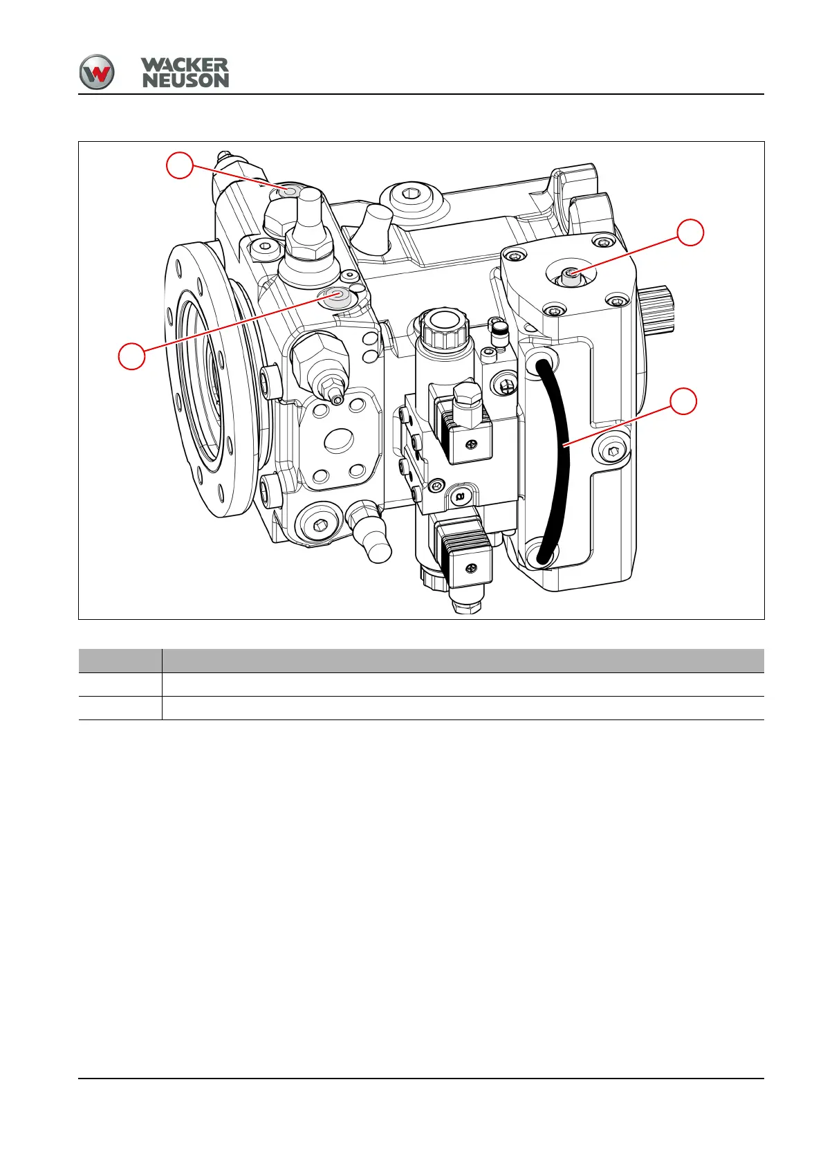
3. Connect both control pistons of the variable displacement pump via
hose 11 with a nominal width of at least N6. This is to ensure that the
setting is not affected by a residual signal from the control unit.
4. Connect test pressure gauge (0–600 bar) to the measurement
connections M
A
and M
B
.
5. Start the engine.
6. Keep the travel direction selection in zero position.
7. Press the gas pedal and read the pressures off both pressure gauges.
Both pressure gages show the same pressure:
➥ The mechanical zero position is adjusted correctly.
The pressure gages show different pressures:
➥ Adjust the mechanical zero position with adjusting screw 4.
Item Description
4 Adjusting screw
11 Hose with minimal nominal width NW 6